
Photovoltaic Power System and Wiring Module Interconnection

The photovoltaic power system described in this manual serves as a comprehensive resource for those involved in the design and implementation of solar energy solutions. The manual emphasizes the importance of adhering to the 2005 National Electrical Code (NEC) to ensure safety and efficiency in PV system installations.
The sections dedicated to photovoltaic modules provide critical insights into their proper marking and wiring practices. Discussions on module interconnection detail the methods to effectively connect multiple modules to form a PV array, ensuring optimal performance and reliability. The inclusion of tracking modules highlights advancements in PV technology that allow for increased energy capture by following the sun's path throughout the day.
Ground-fault protection is a significant aspect of the manual, addressing the necessary measures to prevent electrical faults that could pose safety risks. Grounding techniques are elaborated upon, detailing the specifications for DC grounding electrode conductors and points of connection, which are essential for maintaining system integrity and safety.
The manual also outlines the requirements for various components such as charge controllers and inverters, which are critical for managing energy flow and conversion within the system. It delves into the selection of conductors, emphasizing copper due to its advantageous properties, while also providing guidance on conductor ampacity to ensure that the wiring can handle the expected electrical loads without overheating.
Overall, this manual serves as an essential guide for engineers, installers, and technicians in the photovoltaic industry, offering a thorough understanding of the components, configurations, and safety protocols necessary for effective solar energy systems.Photovoltaic (PV) is the field of technology and research related to the application of solar cells for energy by converting sunlight directly into electricity. The following Photovoltaic Power System manual is a suggested practices manual examines the requirements of the 2005 National Electrical Code (NEC) as they apply to photovoltaic (PV) power
systems. In this manual you will get the design requirements for the balance-of-systems components in a PV system are addressed, including conductor selection and sizing, overcurrent protection device rating and location, and disconnect rating and location. This manual is divided into sections which covers discussion on Photovoltaic Modules (including Modules Marking, Wiring, Module Interconnection, Tracking Modules, Terminals, Transition Wiring, Module Connection Access, Module Connectors, and Splices), Conductor Color Code, PV Array Ground-Fault Protection, PV Array Installation and Service, Grounding (including size of DC grounding electrode conductor, point of connection, charge controller, ungrounded system), Equipment Grounding, Inverter AC Outputs, Conductor Ampacity, Overcurrent Protection, Batteries, Generators, Charge Controller, Inverters, Stand Alone Distribution System, etc.
Copper conductors are recommended for almost all photovoltaic system wiring. Copper conductors have lower voltage drops and better resistance to corrosion than other types of comparably sized conductor materials. Aluminum or copper-clad aluminum wires can be used in certain applications, but the use of such cables is not recommended ”particularly in dwellings.
All wire sizes presented in this guide refer to copper conductors. 🔗 External reference
Related Circuits
Hysteresis in a lamp dimmer or other electrical appliances may cause issues when fine-tuning, leading to a feeling of being out of control. This is a circuit of. Hysteresis in dimmer circuits can lead to undesirable fluctuations in brightness levels,...

The following circuit is a power amplifier circuit for an FM transmitter with an output power of 30 watts. The power amplifier circuit utilizes a power transistor of type 2SC1946A. The FM transmitter operates with a 13.8-volt DC power...
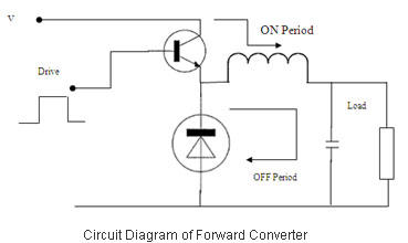
Switched Mode Power Supplies (SMPS) are categorized as DC to DC converters and DC to AC converters. Switched Mode Power Supplies (SMPS) are essential components in modern electronic devices, providing efficient power conversion from one form to another. The primary...
This circuit functions as a night lamp when a wall mains socket is unavailable for plugging in a continuously operating small neon lamp device. To minimize battery consumption, it utilizes a single 1.5V cell, and a simple voltage doubler...
The supply receives -20 V from the rectifier/filter which is fed to the collector of the Darlington pnp pass transistor, a TIP105. The base drive to the TIP105 is supplied through resistor R5. The base of the TIP is...
An RF force amplifier for FM is essential for amateurs looking to enhance small transmitters, whether they are homemade or commercially available. The presented circuit can deliver 50-60W of RF power with an input control of 15-20W within the...