
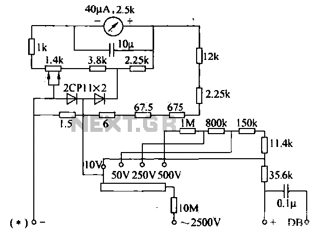
Adjustable output voltage of the series regulator circuit diagram

The described circuit employs a potentiometer to facilitate the adjustment of the output voltage. The 2.5k ohm potentiometer serves as a variable resistor, enabling fine control over the current flowing through it. When the reference current of approximately 7mA is established, the voltage across the potentiometer can be calculated using Ohm's Law (V = I × R). As the resistance is varied, the voltage drop across the potentiometer changes, thus allowing the output voltage (Ua) to be modulated between zero and its maximum value.
In practical applications, this configuration is commonly used in power supply circuits where a variable output voltage is required. The constant current source ensures stability in the output, preventing fluctuations that could arise from varying load conditions. Additionally, the use of a potentiometer allows for easy manual adjustments, making it suitable for applications where precise voltage settings are necessary.
To enhance the performance of this circuit, consideration should be given to the power ratings of the components used, particularly the potentiometer, to ensure they can handle the maximum current without overheating. Furthermore, circuit protection mechanisms, such as fuses or current limiting resistors, may be incorporated to safeguard against potential overload situations. Overall, this circuit design offers a reliable solution for applications requiring adjustable voltage outputs. Circuit output voltage can be continuously adjusted from zero to maximum. Its baseline is a constant current from the auxiliary power supply circuit. 500 Europe reference curre nt can be adjusted to fine-tune the resistance, and its value should be around 7mA. This current flows through the 2.5k Europe potentiometer and the voltage drop is formed from zero to maximum output voltage thereon, so that the output voltage Ua can be continuously adjustable from zero to maximum.
Related Circuits
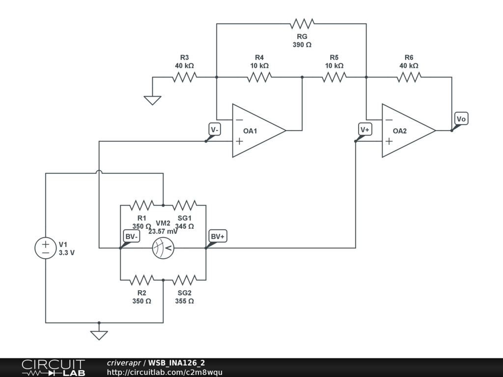
A half-bridge setup is utilized with strain gauges and an INA126 to amplify the voltage. The voltage can be read accurately when the lever is bent in one direction; however, no reading is obtained when the lever is bent...
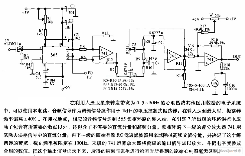
The circuit is designed for satellite transmission of ECG signals with a bandwidth range of 0.5 to 50 Hz, as well as other medical data within electronic systems. An audio signal serves as the FM signal source, which is...
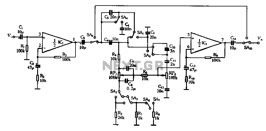
Figure 4-13 illustrates a modified version of a standard attenuated tone control from the pitch selector. It features two amplification stages of amplifiers 10 and Icl utilized as line amplifiers. Capacitor C2 is employed to compensate for tone attenuation...
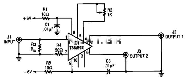
This circuit selects one of two channels using a logic signal. The unused channel is shorted out to minimize crosstalk. The bandwidth at -3 dB is approximately 8 MHz. It is recommended to buffer this circuit due to some...
The voltage converter can be configured to switch between AC voltage ranges using a selector switch. The measurement circuit is depicted in the accompanying figure. In this configuration, a shunt resistor is placed in parallel with the header, maintaining...
Gadget Master provides the latest updates on capacitance circuits in a compilation of capacitance circuit projects and websites tailored for electronics designers, scientists, and engineers. Capacitance circuits are fundamental in various electronic applications, serving critical roles in timing, filtering, and...