
PIC IR Decoders

The PIC IR decoder circuit is designed around the PIC16F84 microcontroller, which serves as the central processing unit. The microcontroller is powered by a standard supply voltage, typically 5V, and requires a 4.000 MHz crystal oscillator for timing precision. The reset circuitry is vital for initializing the microcontroller upon power-up, ensuring reliable operation.
The IR receivers used in the project are tuned to different carrier frequencies, allowing for compatibility with a variety of IR remote control protocols. The combination of the two receivers helps enhance the system's sensitivity and reliability. The signals from the receivers are rectified and combined via diodes to ensure that the microcontroller receives a clean and stable input signal at PORTA bit 4.
The inclusion of a push button provides potential for future expansion, allowing users to select different IR protocols through software modifications. This flexibility can be beneficial for applications requiring interaction with multiple remote controls.
The multiplexed 4-digit LED display simplifies the visual output of the system, allowing users to easily read information. The use of PNP transistors for driving the common anodes is a common practice in LED multiplexing, as it allows for efficient control of the display segments. The resistors limit the current to prevent damage to the LEDs while ensuring adequate brightness.
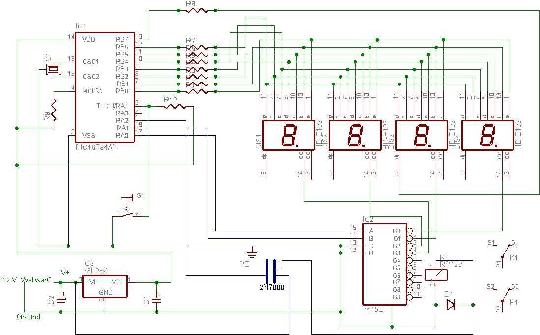
The choice of pad board for assembly aids in rapid prototyping, allowing for modifications and adjustments as needed. This method is particularly advantageous for hobbyists and engineers looking to create a compact and functional prototype without the need for a custom PCB design. Overall, the PIC IR decoder project exemplifies a straightforward approach to building a versatile and user-friendly IR communication system.All PIC IR Decoders share the same, easy to build, hardware. All parts for this hardware are easily obtainable throughout the world. Building it shouldn`t take very much longer than one evening. At the heart of the diagram is the PIC16F84 processor. It is accompanied by its standard components like a 4. 000 MHz crystal and reset circuitry. BTW a PI C16C84 works equally well, just in case you have them lying around like I do. I have used two types of IR receivers in this project, one tuned to a 36 kHz carrier and the other to 38 kHz. This ensures adequate sensitivity for all supported protocols. It`s no problem if you can`t get your hands on the exact same types that I have used. There are plenty of similar receivers out there which can be used in exactly the same way. The signals of both receivers are added together by 2 diodes before they are applied to PORTA bit 4 of the PIC.
Be sure to connect a 22 µF capacitor close to the supply pins of each of the receivers. The push button, which is also connected to the same input of the PIC, has no function at the moment. I`ve included it just in case I decide to create a program that can read multiple IR protocols. The push button can then be used to select the protocol. The LED display concludes the description of the diagram. It is simply a multiplexed 4 digit LED display. I`ve used one with 4 digits in one package because it is far easier to wire than 4 separate one digit displays.
The individual segment current is limited by eight 180 © resistors. The common anodes of the 4 displays are driven by four PNP transistors. If you can`t find the type that I`ve used you can use practically any other PNP transistor which can drive about 200 mA. As usual I`ve built my device on a piece of pad board with road-runner wire. No normal PCB is designed for it. Building on pad board has the advantage that it fast, easy and compact. My board measures only 7x4 cm. Building the PIC IR Decoder requires no special skills. As far as I can see there are no pitfalls in this project. The only thing that I should mention (again and again) is to place the decoupling capacitors as close to the supply pins of the IC`s as possible.
Both IR receivers are IC`s too, you know! 🔗 External reference
Related Circuits
I tried to design a timer that would do everything it needed to do but with the smallest number of pieces and simplest mode of operation. It only needs the PIC, a four digit LED display, one other IC,...
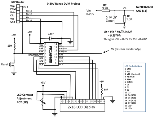
This project details the construction of a digital voltmeter utilizing a PIC microcontroller. A character-based HD44780 LCD display is employed to visualize voltage measurements. The microcontroller selected for this project is the PIC16F688, which features 12 I/O pins, with...
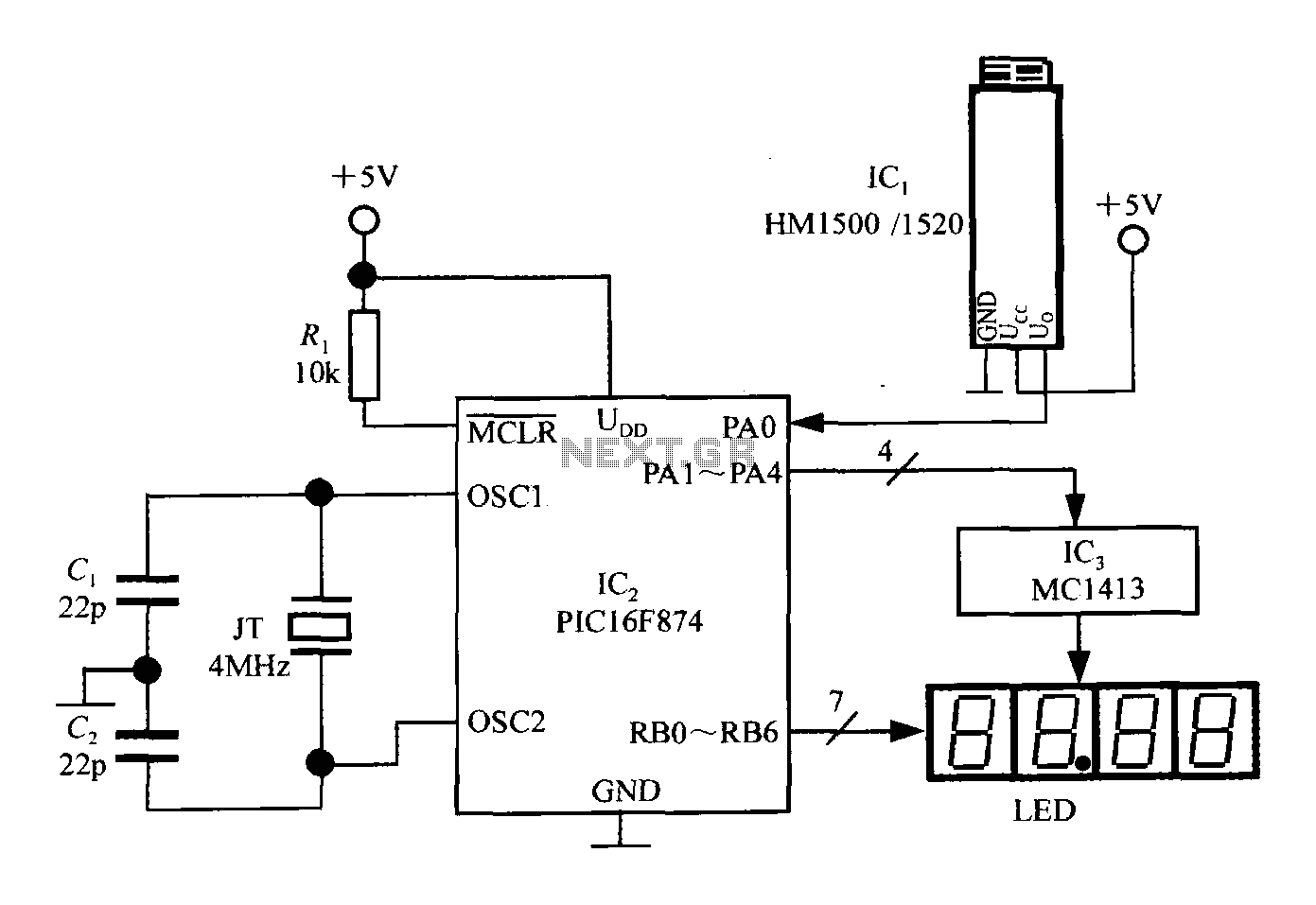
An intelligent humidity meter circuit utilizing the HM1500/1520 humidity sensor and a microcontroller configuration. The circuit operates on a +5V power supply and incorporates four common cathode LED digital displays. It employs three integrated circuits: IC1 is the HM1500/1520...

The IR Widget captures infrared signals used by remote controls and can determine the carrier frequency while demodulating it in either the digital or analog domain. The captured data can be utilized to reproduce or recognize the signal. The...
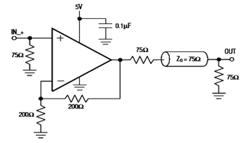
The diagram below illustrates a typical operating circuit for the video line driver using the IC4030/4031 schematic. It incorporates the MAX4030E/MAX4031E, which are unity-gain stable operational amplifiers that offer high-speed performance, rail-to-rail outputs, and 15kV ESD protection, as stated...
The idea behind this project is to provide some means of loading a program into a PIC that will then be able to program other PICs in a more conventional way. How do you program a PIC to be...