
IC4030-4031 Typical Operating Circuit Schematic and Datasheet

The circuit schematic features the MAX4030E/MAX4031E operational amplifiers configured to drive video signals effectively. These amplifiers are designed to operate with a wide supply voltage range, allowing them to be integrated into various video applications. The rail-to-rail output capability ensures that the output voltage can swing close to the supply rails, maximizing the dynamic range of the video signal.
In this configuration, the input stage typically includes a differential signal input to minimize noise and enhance signal integrity. The output stage is designed to drive a standard video load, which may include coaxial cables or other transmission mediums. The high-speed performance of the MAX4030E/MAX4031E makes them suitable for applications requiring fast signal transitions, such as high-definition video transmission.
The 15kV ESD protection feature is critical in safeguarding the circuit from electrostatic discharge, which can occur during handling or operation. This protection ensures the longevity and reliability of the circuit in various environments.
Overall, the schematic demonstrates a robust design for video line driving applications, leveraging the advanced features of the MAX4030E/MAX4031E operational amplifiers to deliver high-quality video signals with minimal distortion and maximum protection against electrical interference.The diagram below shows video line driver typical operating circuit for the IC4030/4031 schematic. It uses the MAX4030E/MAX4031E with such unity-gain stable op amps combine high-speed performance, rail-to-rail outputs, and 15kV ESD protection, according to the datasheet 🔗 External reference
Related Circuits
This PC fan controller circuit is designed with discrete components to control 12V fans that consume less than 200mA. The specified component values in the circuit diagram ensure that the voltage will not drop below 7V. If the fan...
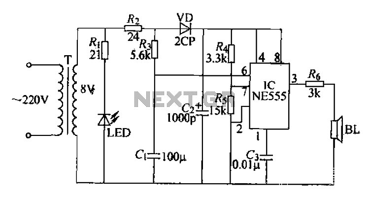
Electrical pulses are generated by the output of the first base circuit pin and sent through the R6 piezoelectric speaker, which converts the electrical pulses into ultrasonic waves. The circuit operates on a simple sweep principle, utilizing the transformer’s...
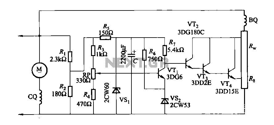
The DC generator automatic voltage regulator circuit is illustrated in Figure 7-53. This circuit is designed for a 40kW, 230V DC shunt complex machine, with a voltage change rate of up to 2.5 percent. In Figure 7-53, BQ represents...
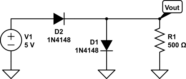
The two diodes will fail. It is advisable to include series resistors for them. If the simulation is successful, the current through the diodes will be excessive. Both diodes do not necessarily need to fail; one may become a...
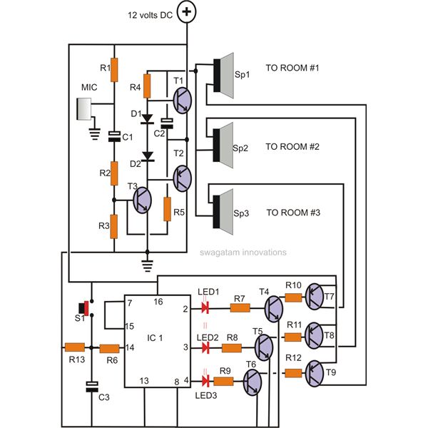
A home intercom system can be constructed using a versatile circuit design. This system allows communication across up to ten different locations or rooms discreetly. It utilizes a single changeover switch for selecting the desired location, replacing the traditional...
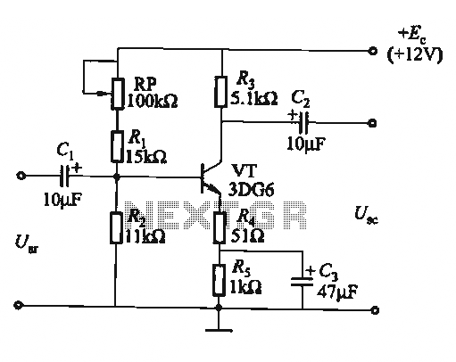
The circuit is a bias circuit for automatic stabilizers that maintains a stable quiescent operating point with good thermal stability. It utilizes a three-pole tube with an NPN type transistor, characterized by a small Iceo. An adjustment potentiometer, RP,...