
Pic-Plot : a GPIB to RS-232 converter

The described adaptor serves as a bridge between GPIB (General Purpose Interface Bus) instruments and a PC, utilizing the PIC16F628A microcontroller for processing and control tasks. The GPIB interface is commonly used in test and measurement equipment, allowing for communication between devices. The primary function of this adaptor is to capture graphical data, such as plots or prints, from GPIB-enabled instruments and transmit this data to a PC via a serial RS-232 connection.
The PIC16F628A microcontroller is programmed to emulate the operations of the HP7470A plotter, which is a widely recognized device in the field of graphical data output. By mimicking the commands and data protocols of the HP7470A, the adaptor can seamlessly interact with various GPIB instruments, ensuring compatibility and ease of use. The microcontroller processes incoming GPIB commands and translates them into HP-GL (Hewlett-Packard Graphics Language) data, which is then formatted for output through the RS-232 port.
The RS-232 interface is a standard serial communication protocol that facilitates data transfer between the adaptor and the PC. This allows users to capture and store graphical representations of their test data using any compatible software that can interpret HP-GL format. The versatility of this adaptor extends beyond simple plotter emulation; it can also handle various types of data intended for graphical representation, making it a valuable tool for engineers and technicians who require detailed visual outputs from their instruments.
In summary, this adaptor provides an efficient solution for capturing and transferring graphical data from GPIB instruments to a PC, leveraging the capabilities of the PIC16F628A microcontroller to ensure smooth operation and broad compatibility with existing software.This adaptor will capture plots or prints of your GPIB instrument to your PC through the serial port. It fills the need of anybody who has a test instrument with the GPIB port and likes to get the screen dump on his PC without any GPIB card.
Project based on a PIC16F628A microcontroller. The Pic-plot emulates the HP7470A operation on the GPIB side, and outputs the HP-GL data at the RS-232 port to be read and stored on the PC by any suitable software. The operation of this interface is not just limited to plotter emulation: any data intend 🔗 External reference
Related Circuits
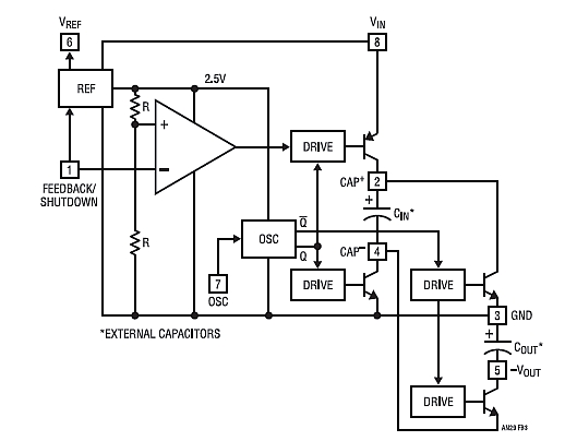
Chapter 4, part five of a five-part series titled "Some Thoughts on DC/DC Converters," authored by the late Jim Williams and Brian Huffman, is included in Volume II of the book "Analog Circuit Design-- Immersion in the Black Art...
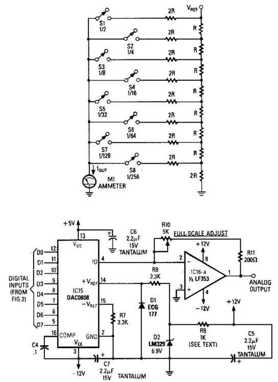
Figure A illustrates an R/2R resistor ladder. Each closed switch increases the current output. A basic channel A/D converter is depicted in Figure B. The voltage reference (D2) is shared among all channels, while the value of the dropping...

A voltage-to-frequency converter with a control range of 1:1000 can be constructed using the IC TSC9402. The specified component values in the circuit yield a conversion factor of 1 kHz per 1 V. Input voltages ranging from 10 mV...
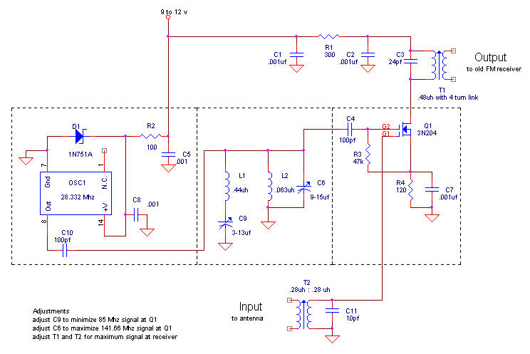
The FM broadcast band was relocated immediately after World War II from its original frequency just below 50 MHz to the current 88-108 MHz range. Hallicrafters was one of the companies that provided receiving converters for users of older...
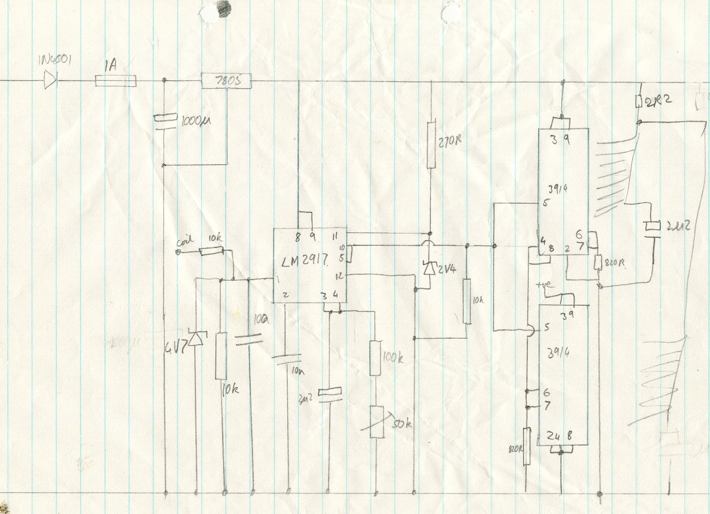
This circuit utilizes an LM2917 frequency-to-voltage converter. The input is connected to the low voltage side of the ignition coil, with various components designed to produce a full-scale output at 6000 RPM, corresponding to 12000 ignition pulses per minute,...
In need for a cheap but effective RS-232 Protocol Analyser? Just make your own Y adaptor to enable the logging or display of data transmitted and/or received in ASCII, Hex, Decimal or Hex-Dump formats. A configuration file is included...