
RS-232 Protocol Analyser Y Cable

To construct a simple yet effective RS-232 Protocol Analyser using a Y adapter, the circuit design primarily revolves around a standard RS-232 interface, which operates with voltage levels typically ranging from +3 to +15 volts for logic high and -3 to -15 volts for logic low.
The Y adapter consists of a pass-through cable with three connectors: one for the RS-232 device under test and two for connecting to a secondary computer equipped with a Protocol Analyser Software. The cable should be wired to maintain the integrity of the TXD (Transmit Data) and RXD (Receive Data) lines, allowing for simultaneous monitoring of both data streams.
The wiring configuration involves connecting the TXD line from the device under test to the RXD input of the secondary computer and the RXD line from the device under test to the TXD input of the secondary computer. Ground connections must also be established to ensure a common reference point for signal integrity. It is advisable to use shielded twisted pair cables to minimize noise and interference, especially in environments with high electromagnetic interference.
The configuration file provided with the analyser software facilitates quick setup by defining parameters such as baud rate, data bits, stop bits, and parity settings. This allows the user to adapt the software to the specific communication settings of the RS-232 device being monitored.
For effective data logging and analysis, the Protocol Analyser Software should be capable of displaying data in various formats, including ASCII, Hex, Decimal, and Hex-Dump, enabling detailed inspection of the communication protocol in use. This flexibility is crucial for debugging and optimizing serial communication in various applications.
Overall, this DIY Y adapter solution provides an economical and efficient means of monitoring RS-232 communications, making it an invaluable tool for engineers and technicians working with serial interfaces.In need for a cheap but effective RS-232 Protocol Analyser? Just make your own Y adaptor to enable the logging or display of data transmitted and/or received in ASCII, Hex, Decimal or Hex-Dump formats. A configuration file is included to allow quick setup and analysis. You can make your own "Y" cable by following the diagram below. It consists of a pass-through cable which is connected in-line with the link under test. The TXD and RXD lines are broken out and sent into a second "Protocol Analyser" computer via two com ports, each monitoring one line each. The second computer then runs the Protocol Analyser Software. 🔗 External reference
Related Circuits
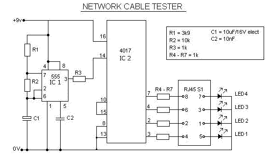
This is a multifunction RJ45 network cable tester designed for testing network cables (RJ45) and telephone cables (RJ11). It is cost-effective and user-friendly. The tester determines whether a network cable is a crossover or straight type by illuminating a...
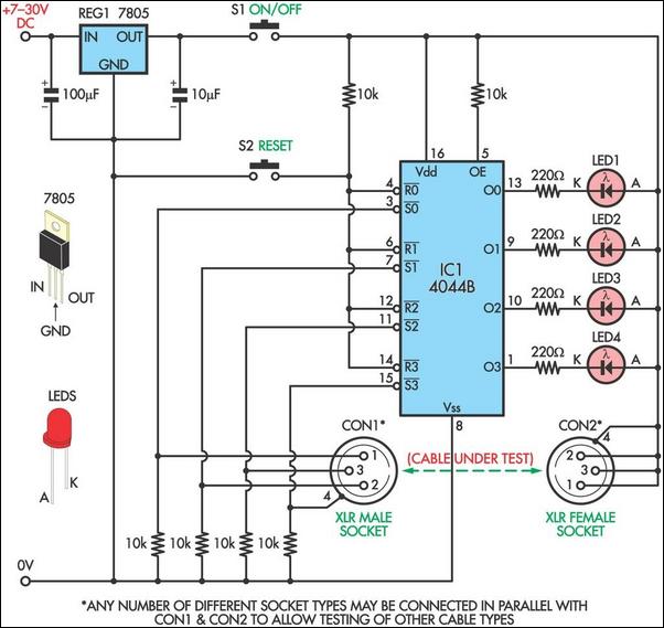
This circuit is designed to facilitate the testing of microphone cables or other types of cables for intermittent breaks that are often challenging to detect with a multimeter. The circuit can accommodate cables with up to four cores. It...
A PC sync cord can be created from an extension cable by incorporating a connector and attaching different plugs on the opposite end. This setup includes an isolation circuit housed in a CF case, which ensures that high voltage...
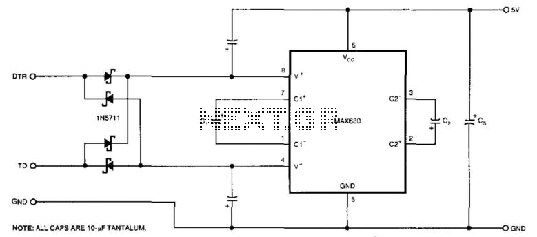
The circuit demonstrates a method for powering CMOS integrated circuits (ICs) using RS-232C lines. The MAX680 is typically employed to generate a voltage equal to ±2 Vcc. This circuit operates in the opposite manner, accepting ±10.5 to ±12V from...
The following circuit is an example of how to get power from an RS-232 serial port. It provides regulated +5V power for logic circuits and also unregulated positive and negative power supplies for the RS-232 transmitting circuit. The circuit...
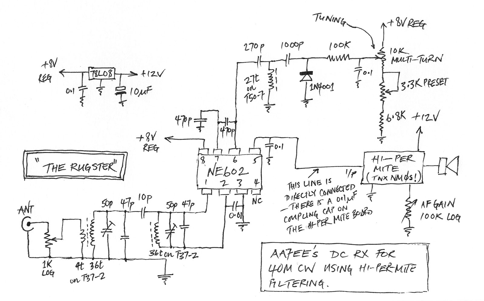
This section describes an experimental low power, low bandwidth data signaling system that operates at 100 MHz (In the FM broadcast band in the U.S.). Before operating a radio transmitter, find out what kind of transmitter operation, if any,...