
PIC Programmer

The uJDM PIC programmer is a compact and efficient circuit used for programming a range of Microchip PIC microcontrollers. It operates through a USB interface, allowing it to connect directly to a computer for programming tasks. The circuit typically includes a few key components: a USB connector, a microcontroller interface, and various passive components such as resistors and capacitors that facilitate programming operations.
The core of the uJDM programmer is a dedicated microcontroller that manages the communication between the computer and the target PIC microcontroller. This microcontroller translates the programming commands from the software running on the computer into the appropriate signals required to program the target device. The circuit is designed to support multiple PIC variants, making it versatile for different applications.
For operation, the programmer connects to the target PIC microcontroller via a set of pins that correspond to the programming interface of the PIC device. These pins typically include Vpp (programming voltage), Vdd (operating voltage), and several data lines for communication. The circuit is powered through the USB connection, which simplifies the setup and eliminates the need for an external power supply.
The schematic of the uJDM PIC programmer will include the necessary connections and component values to ensure reliable operation. It is important to follow the schematic closely to avoid damage to the microcontroller or the programmer itself. Additionally, the programmer's software must be compatible with the target microcontroller to ensure successful programming.
In summary, the uJDM PIC programmer circuit is an essential tool for developers working with Microchip PIC microcontrollers, providing a straightforward and effective method for programming various PIC models.PIC Programmer Circuit diagram Following uJDM PIC programmer circuit is a circuit which suitable to do simple pic16f84, pic16f84A, 16c84,.. 🔗 External reference
Related Circuits
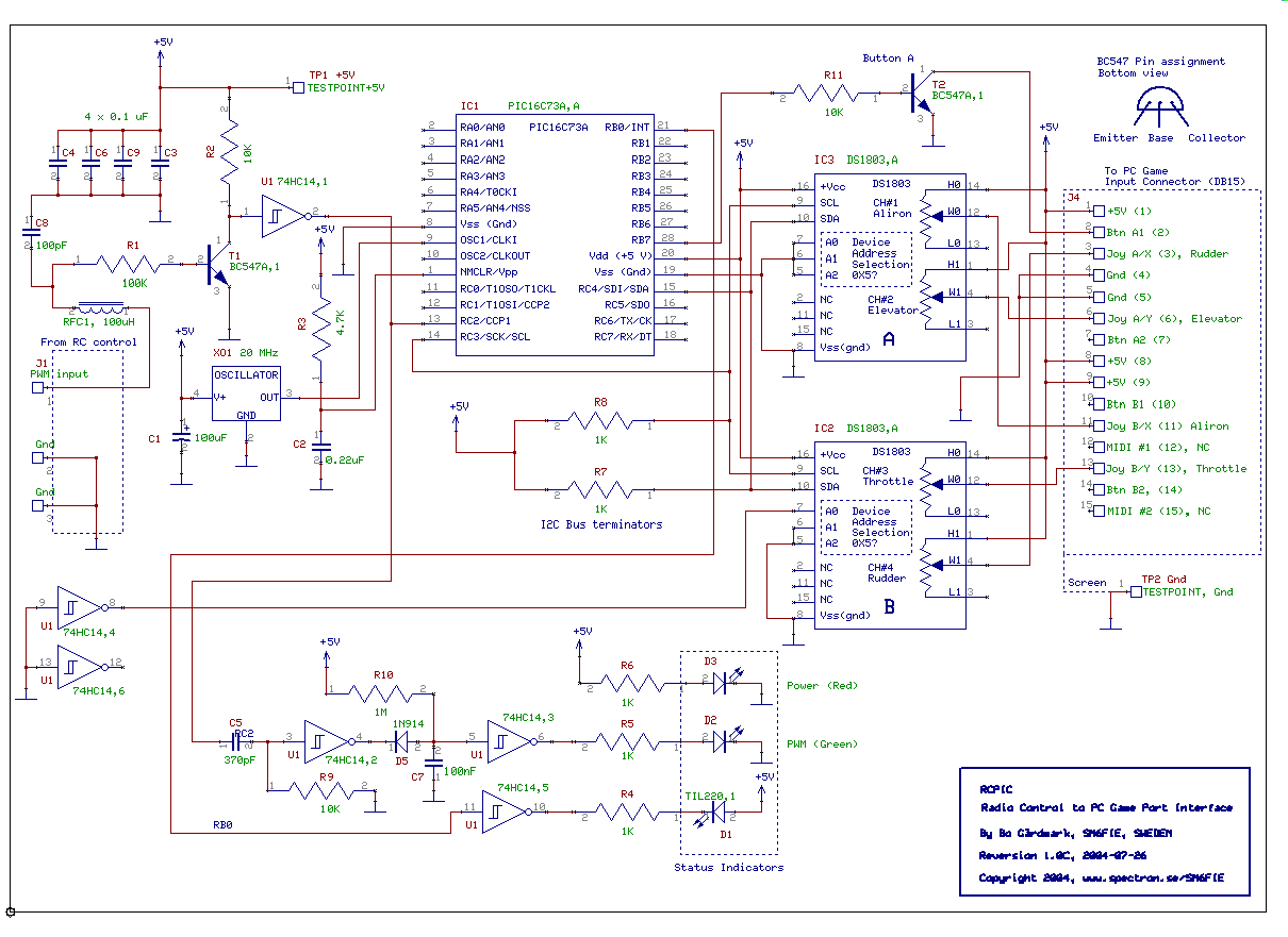
This circuit interfaces a standard RC control to a standard PC game port. The primary objective was to utilize the interface for the FMS flight simulator, allowing a standard RC radio to control the FMS flight simulator under Microsoft...
The chassis is constructed from aluminum L-profile measuring 30x30x2 mm, while the candles are made from 13 mm aluminum pipes. The overall structure measures approximately 35 cm in width and 25 cm in height, assembled using a two-component adhesive....
The LED blinks as expected, then pauses for an indefinite duration, flashes again a different number of times, and turns off again, displaying no discernible cyclic behavior. It activates without any external input, indicating that there is likely no...
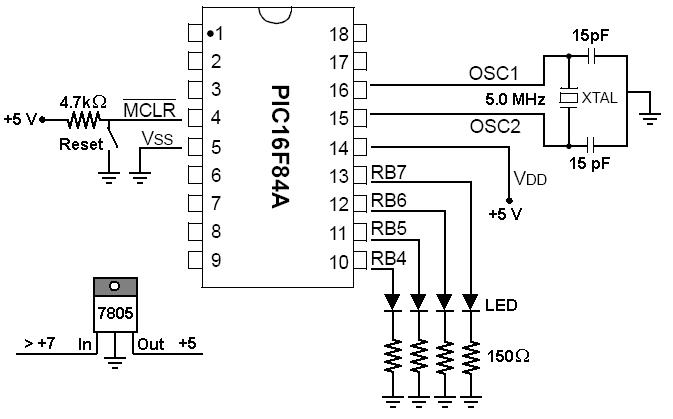
To start working with microcontrollers, several essential items are required. The PICSTART Plus kit, part number DV003001, was purchased from Microchip. This kit contains a sample PIC16F84 microcontroller chip, which in this case is a PIC16F84A chip. This chip...
This scanner uses a DDS circuit to scan through the frequency band. Since a DDS is used to set the desired frequency, this receiver can jump from one frequency to another within microseconds, making it very fast. The receiver...
This project uses only a few of the instructions that come with PicBasic, but serves to show how easy PicBasic really is. It also shows how PicBasic strongly resembles programming the BASIC Stamp. Here we are using the serin...