
RC PIC

The circuit design focuses on enabling seamless integration between a standard RC transmitter and a PC game port, facilitating control of flight simulation software. The microprocessor's role is crucial, as it processes the incoming PWM signals and translates them into digital commands that modulate the resistive values of the DS1803 digital potentiometers. This modulation allows for fine control of the simulation parameters, effectively mirroring the physical movements of the RC transmitter's control sticks.
The use of a Harvard architecture microprocessor allows for efficient handling of the pulse measurement tasks, as it can simultaneously access program instructions and data. The choice of the 16C73A microprocessor provides adequate processing power for the required tasks, ensuring timely response to user inputs.
The RF filtering stage is essential for maintaining signal integrity, especially in environments where electromagnetic interference may be present. By incorporating a coil and capacitor filter, the circuit minimizes the potential for erroneous readings caused by noise, thereby enhancing the reliability of the system.
The implementation of the DS1803 dual digital potentiometer is particularly advantageous, as it provides a high level of precision in controlling the simulated aircraft's parameters. The I2C interface for communication with the microprocessor simplifies the design, allowing for easy expansion or modifications in future iterations of the circuit.
Overall, this circuit serves as a robust solution for interfacing RC controls with flight simulation software, demonstrating the effectiveness of integrating traditional RC technology with modern computing interfaces.This circuit interfaces a standard RC-control to a standard PC game port, see figure 1. The main target was to use the interface for the FMS flight simulator. The interface makes it possible to use a standard RC radio to control the FMS flight simulator under Microsoft Windows 2000 and XP. Of course, it also works under Win95, ME, 98. As long as y ou have a working game port (joystick port) on your PC you can use this interface. The system was developed and tested with a Hitec Flash-5X (35M) Digital Proportional Radio Control system, see figure 2. However, it should work without any modification with most RC controllers. The RC Transmitter (controller) sends a PWM (Pulse Width Modulated) signal to the receiver. The PWM signal is also sometimes called PPM (Pulse Position Modulation). The receiver decodes the signal and uses the signal to control servos etc of the model in use. The PWM signal is illustrated in figure 3. As can be seen by the figure a frame is built up of a number of channels, in this case four channels.
The frames a repeated with about 50 frames a second. The circle in figure 3 focus on channel one in the frame. In figure 4 you find an enlarge picture of just that cannel. As you see in figure 4 the channel time is divided by two parts. TLow is always the same length and is about 0. 5 mille seconds. THigh on the other hand is variable between 0. 5 and 1. 5 mille seconds. The Thigh time depends on the position of the stick on the RC-control (transmitter). As you can see the timing changes from 0. 5 to 1. 5 mille seconds. By measuring the THigh time for each channel in the frame, we have a measurement of the position of the sticks. This is exactly what the electronics in RCPIS does. It does this by a help of a microprocessor. For a full explanation and tutorial about the RC concept see the references in the end of this description or follow this link.
See schematic schema in figure 7, you can click on the picture to enlarge it in a separate window. You can also download the schematic by clicking on this link. The interface takes the PWM (Pulse Width Modulated) signal from the trainee connector. This is a standard built in connector of the Hitec-5X RC control. The cable from the RC controller is connected to the J1 connector on the interface. The PWM signal and ground is only connected to connector J1. The input circuit with T1 and IC U1 is a buffer and pulse shaper, see schematic The output from the pulse shaper is directly feed to the microprocessor. To remove any RF a HF filter is inserted before transistor T1. The filter consists of RFC 1 (coil) and capacitor C8 (220 pF) The heart of the circuit is the 16C73A microprocessor.
This is a 8-bit RISC processor with a Harvard architecture. The clock speed is 20 MHz and the clock signal is generated of the X01 oscillator. This clock is used as a reference clock too measure the channel pulses described above. The processor measures the pulse width for each channel (up to four channels) and uses the measurement to control four digital controlled resistors (DS1803). The DS1803 Addressable Dual Digital Potentiometer is an addressable device having two independently controlled potentiometers.
Each potentiometer`s wiper can be set to one of 256 positions. This gives a smooth control over the aircraft. Device control is achieved via a 2-wire I2C serial interface having a data I/O terminal (SDA) and a clock (SDC) input terminal. Device addressing is provided through three chip select input terminals and correct communication protocol.
The output from the DS1803 circuit is connected to a PC standard game port connector. The game port has a 15 pin connector. There are three LEDs indicating the status of the electronics. On PWR (red) indicates if power is applied to the electronics. The card takes the power from the game port (PC-computer) so there needs not to be any external power connection. > The PWM L 🔗 External reference
Related Circuits
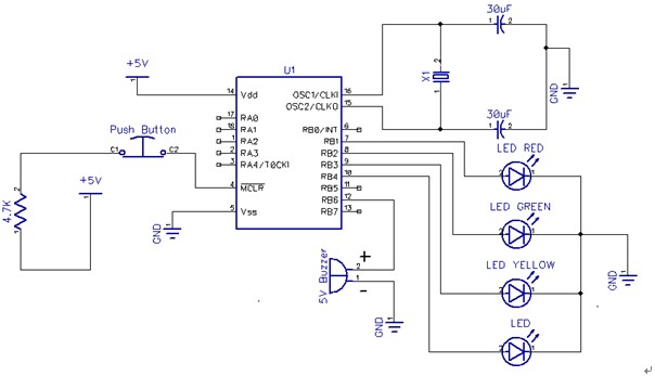
The circuit this month is a simple 8 light chaser built around a PIC. This will demonstrate how easy it is to program a PIC and to utilize it in a circuit. The circuit works as follows. When power...
All resistors are 1/4W. The circuit is powered by 9...15V DC or AC. When In Circuit Programming (ISP) connectors are used, it is possible for the programmer to be powered from the target's power source. Diodes D2 and D6...
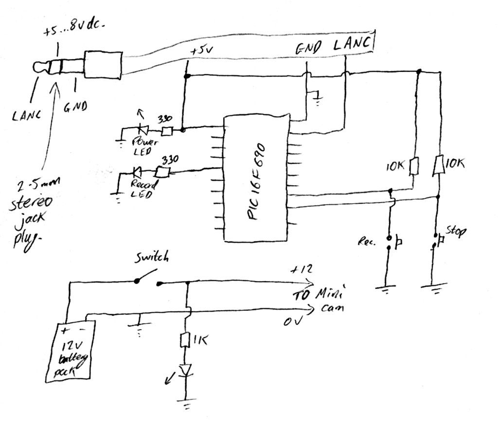
Inexpensive PIC-controlled helmet camera utilizing Sony LANC, suitable for extreme sports. This guide will demonstrate how to create an affordable helmet camera. The proposed electronic schematic involves a PIC microcontroller interfaced with a Sony LANC (Local Application Control Bus) to...
After answering all relevant questions and obtaining the necessary decisions, a thorough study of the PIC datasheet is essential to understand the steps for each configuration and other details. It is important to note that it is bit 3...
This oscillator is known as the Colpitts oscillator and is voltage-controlled to facilitate frequency modulation (FM) and phase-locked loop (PLL) control. The transistor T1 should be a high-frequency (HF) transistor for optimal performance; however, in this instance, a common...
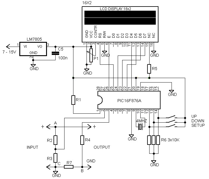
A voltmeter and ammeter using a PIC microcontroller can measure voltage and current simultaneously. This setup employs a PIC16F876A as the data processor for voltage and current measurements. An LCD display (16x2) is utilized to present the measured voltage...