
pic sound player pcm to pwm converter using pic18f1320

The project utilizes a PIC microcontroller, which is programmed to generate audio signals through pulse-width modulation (PWM). In this setup, the microcontroller converts digital audio data into an analog signal that can be output to a speaker or other audio transducer. The PWM technique allows for the simulation of varying audio amplitudes by rapidly switching the output voltage between high and low states, effectively creating a series of pulses that represent the audio waveform.
The core of the design involves configuring the microcontroller's timer to generate PWM signals at a specific frequency, which corresponds to the desired audio sample rate. The audio data is typically stored in an array within the microcontroller's memory, and the PWM output is modulated according to the values in this array. As the microcontroller iterates through the audio data, it adjusts the duty cycle of the PWM signal, thereby varying the output voltage and producing sound.
For optimal performance, it is important to filter the PWM output to smooth out the digital signal into a more continuous analog waveform. This can be accomplished using a low-pass filter, which eliminates high-frequency components and allows the desired audio frequencies to pass through. The resulting audio output can then be amplified using an audio amplifier circuit to drive speakers or headphones.
Overall, this project demonstrates the effective use of PWM modulation for audio playback in embedded systems, showcasing the capabilities of PIC microcontrollers in generating high-quality sound from digital audio data.This project makes a PIC microcontroller play audio PCM sounds using PWM modulation! Pulse-code modulation (PCM) is a digital representation of.. 🔗 External reference
Related Circuits
The pins RA3 to RA0 are used as outputs driving each column LED. The pins RB0 to RB7 are used as outputs driving signals for each column LED. The 74HC154 (Decoder 4 to 16) is the chip that decodes...
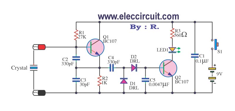
A multimeter cannot be used to test a crystal oscillator. Instead, a dedicated circuit is required, capable of checking crystals within the frequency range of 100 kHz to 900 MHz. This circuit is easy to construct and cost-effective. To construct...
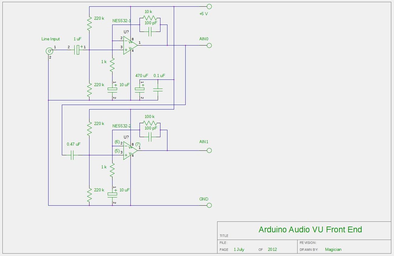
After experimenting with a stereo version of the VU meter described in a previous blog post, a studio-grade VU meter is now being presented. This meter features 24 steps, spaced equally every 3 dB, and covers a wide dynamic...
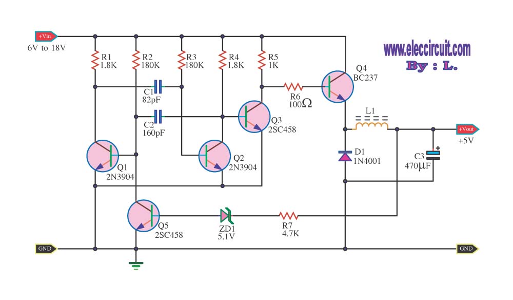
The circuit reduces voltage size or functions as a step-down voltage converter circuit, which is a DC regulated circuit model utilizing a switching converter. This design generates a specific voltage output. The step-down voltage converter, also known as a buck...
If the robot is positioned on the black line, it will continue moving forward. However, if it veers off the line and enters a white area, it will assess whether to correct its path to the left or right,...
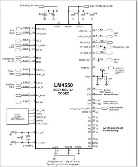
The LM4610 is a DC-controlled tone (bass/treble), volume, and balance circuit designed for stereo applications in car radios, televisions, and audio systems. It also incorporates National's 3D-Sound circuitry, which can be adjusted externally using a simple RC network. An...