
Step down voltage converter 5v with transistor BC337

The step-down voltage converter, also known as a buck converter, is an essential circuit in power electronics, allowing for efficient voltage regulation and conversion. This type of converter operates by switching elements, typically a transistor, on and off rapidly to control the energy transfer to the output. The fundamental components include an inductor, a diode, a capacitor, and a control circuit.
In operation, when the switching element is turned on, current flows through the inductor, storing energy in its magnetic field. When the switch is turned off, the inductor releases the stored energy to the output load through the diode. The output voltage is regulated by adjusting the duty cycle of the switching signal, which is the ratio of the on-time to the total time of the switching cycle.
The design of the circuit must consider several factors, including the input voltage range, the desired output voltage, and the load current requirements. Additionally, the selection of the inductor and capacitor values is critical for ensuring stability and minimizing ripple voltage at the output.
The efficiency of the buck converter is typically high, often exceeding 90%, making it suitable for battery-powered applications where power conservation is essential. Proper thermal management and component selection are crucial to maintain performance and reliability in various operating conditions.
Overall, the step-down voltage converter circuit is a versatile solution for providing regulated DC voltage outputs in a wide range of electronic applications, from consumer electronics to industrial power supplies.The circuit decreases the size voltage or Stepdown Voltage converter circuit be dc regulated circuit model switching converter. The that make voltage output.. 🔗 External reference
Related Circuits
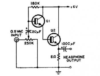
This schematic diagram illustrates a simple headphone amplifier circuit constructed using two NPN transistors. Suitable transistor options include the BC549C, as well as other NPN transistors such as the European equivalents BC548C, BC547C, BC239, 2N5818, or 2N2222. An audio...
The designer requires a 1-Wire host computer IO framework that operates at 1.8V. Most 1-Wire devices are unable to function at this voltage. This application recommends implementing a 1.8V 1-Wire host computer alongside a 5V 1-Wire reference design for...
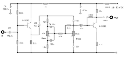
The first BC109C transistor functions as a buffer, delivering a high input impedance of approximately 250k and exhibiting a voltage gain marginally below unity. Given that the Baxendall tone control circuit operates passively, it attenuates all audio frequencies. The...
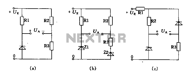
The circuit depicted in Figures A, B, and C demonstrates a high voltage coefficient. When the regulator resistance \( r_z \) is held constant, the bridge configuration achieves an infinite voltage coefficient. In Figure A, the load circuit is...
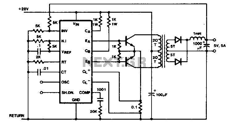
Push-pull outputs are utilized in this transformer-coupled DC-DC regulating converter. It is important to note that the oscillator must be configured to operate at twice the desired output frequency, as the SGI 524's internal flip-flop divides the frequency by...
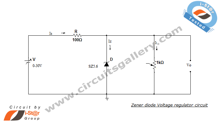
A Zener diode regulator is a fundamental electronic circuit valuable for hobbyists. This circuit provides a regulated output voltage, suitable for biasing other circuit components. The Zener diode operates in the reverse breakdown region, maintaining a nearly constant voltage...