
Basic Transistor Circuits

The circuit operates by utilizing a relay to control larger loads through a low-power signal. The relay coil is energized when the input signal is high, allowing for the switching of devices that require higher voltages or currents than the control circuit can provide directly. A critical aspect of this design is the protection diode, which prevents damage to the transistor from the back EMF generated when the relay coil is de-energized. The calculations for the base resistor and transistor selection ensure that the transistor operates within safe limits, providing adequate current gain to switch the relay effectively.
In applications where the load may vary significantly, such as with an LDR, the inclusion of a potentiometer allows for fine-tuning of the circuit's sensitivity to light changes. The use of a Darlington pair enhances the circuit's capability to drive larger loads while maintaining a low input current requirement, thus enabling the design of touch-sensitive switches or other automation features. The monostable multivibrator function adds versatility, allowing the circuit to respond to transient input signals and maintain a stable output state for a predetermined duration, making it suitable for various timing and control applications. Overall, this circuit design showcases the integration of basic electronic components to create a functional and adaptable system for controlling higher power devices with low-power control signals.This circuit will drive a relay coil from a low power output, usually from an IC like 555 or a TTL/CMOS. It is used to switch high loads or loads that needs AC current to operate. The relay will be actuated when the input of the circuit goes high. The protection diode Dp is used to protect the transistor from the reverse current generated from the
coil of the relay during the switch off time. The values for Rb and Qs vary accordingly. The way to calculate them is: Then we calculate the transistor hFE. It must be at least 5 times the load current IL divided by the maximum output current from the Input to the base of the transistor Then you calculate the base resistor RB, If the input is taken from a component (possible an IC) that uses the same power supply as the transistor (that is Vs), then the form is: The output from a 74LS series TTL IC is required to operate a relay with a 160 Ohm coil. The supply voltage is 12V for the transistor and 5V for the IC. The IC can supply a maximum current of 2mA. A transistor may be connected in a way that will switch on and off a load (RL) according to a sensor.
In our example, the sensor is an LDR. The LDR is a resistor that will change it`s resistance according to the light falling on the sensor. The left circuit will switch on the load when the LDR is in dark, and the right will switch on the load when light fall on the LDR. The potentiometer RS will control the sensitivity of the automation. You should consider using a potentiometer 10Kohms. Also note the resistor on the left circuit labeled RP. This resistor is used to protect the transistor when the potentiometer is switched to low values. This RP should be from 1Kohm to 22Kohms. Select according to your LDR. You should consider using low current loads using this circuit. There is a point that the transistor will not be either on or off. In this case, there is danger overheating the transistor if you have big loads like lamps and motors.
In this case, you should use a second transistor connected as a driver. The Darlington pair consists of two transistors connected as the drawing. This connection have the characteristic of very high current gain. Actually, the overall gain is: A Darlington pair will act exactly as a single transistor only with very high current gain. Also, because there must be at least 0. 7volts in both base-emitter junctions, to switch on a pair like that will need at least 1. 4volts. Darlington pairs are available as complete packages but you can make up your own from two transistors.
The first transistor can be a low power type, but normally the second transistor will need to be high power. The maximum collector current Ic(max) for the pair is the same as Ic(max) for the second transistor. Because a Darlington pair will respond to very small current changes, you can make a touch sensor switch like seen on the schematic left.
The RP is a protective resistor, about 100Kohms, in case of short-circuiting the sensor plates. This circuit will perform a monostable multivibrator. When an input pulse occurs, the output goes high and remains high as per time constant of C1 and R2. While the output is high, the input pulses have no effect on the circuit. Also, If the input is triggered and kept high longer than the time constant of C1 and R2, the output will NOT stay high for longer than C1 R2 time constant. The time constant is: 🔗 External reference
Related Circuits
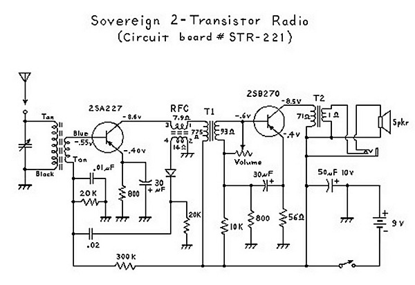
An analysis of certain radios reveals the impressive engineering by Japanese designers, particularly in creating a radio capable of driving a speaker with only two transistors. The first transistor (Q1) serves a dual function; it operates as an RF...
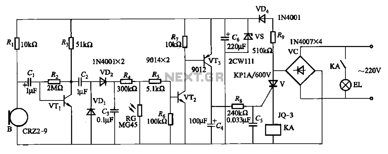
A resistor R8, capacitors Cd, and a thyristor V AC switch form a delay circuit. The lamp's lighting delay time is determined by the resistor Rs and capacitor C4, with a delay of approximately 40 seconds as indicated in...
This circuit generates an FM modulated signal with an output power of approximately 500 mW. The microphone preamplifier is constructed using two 2N3904 transistors, with audio gain controlled by a 5 kΩ preset resistor. The oscillator is a Colpitts...
The circuits in Figure 1 and Figure 2 demonstrate specific advantages over the circuit presented in the Design Idea in EDN, titled "Circuit detects first event," published on May 3, 2001, page 89. The n-player first-event detection circuit provides...
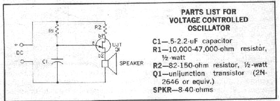
Unijunction transistors are very interesting. They love to be used in oscillators, and it doesn't take too many parts or very much coaxing to get their sawtooth outputs. This little squealer will tell you how much voltage it's connected...
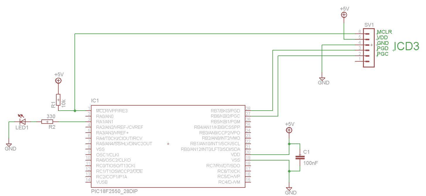
The LED blinks as expected, then pauses for an indefinite duration, flashes again a different number of times, and turns off again, displaying no discernible cyclic behavior. It activates without any external input, indicating that there is likely no...