
PIC16F819 Dymoclock Sensor

The PIC16F819 Dymoclock Sensor Circuit utilizes a PIC16F819 microcontroller, which is a versatile 8-bit device with built-in analog-to-digital conversion capabilities. This circuit is designed to monitor temperature variations and display the readings through LED indicators, making it a cost-effective solution for temperature sensing applications.
The circuit incorporates a low-cost temperature sensor, such as the LM35 or a similar device, which outputs a voltage proportional to the temperature. The microcontroller reads the analog voltage from the temperature sensor using its integrated ADC (Analog-to-Digital Converter). The ADC converts the analog signal into a digital value that can be processed by the microcontroller.
The LED indicators are used to visually represent the temperature readings. Each LED may correspond to a specific temperature range, allowing for a quick visual reference of the current temperature status. The absence of a decoder simplifies the design, reducing component count and potential points of failure, while also minimizing the overall cost of the circuit.
The operation of the circuit can be programmed using the PIC16F819's built-in features, allowing for flexibility in adjusting the temperature thresholds and LED indications. This makes the Dymoclock Sensor Circuit an ideal choice for applications where simple temperature monitoring is required, such as in weather stations, HVAC systems, or educational projects.
Overall, the PIC16F819 Dymoclock Sensor Circuit is a practical and efficient design that leverages the capabilities of the PIC microcontroller to create an effective temperature sensing solution with minimal components.The following circuit shows about PIC16F819 Dymoclock Sensor Circuit Diagram. Features: a cheap temperature sensor, only LEDs, no decoder, built .. 🔗 External reference
Related Circuits

The final step involves connecting the IR LEDs, resistors, and IR receivers to the Arduino. Begin by connecting the +5V pins of the IR receivers (the right pin when facing the receiver) with red wires directly to the +5V...

This is a simple circuit designed to detect electromagnetic radiation, including hidden wiring. It utilizes a 1mH inductor to sense the electric field. The induced voltage from the inductor is amplified by an operational amplifier (op-amp). An audio headset...

For several years, a rear fog lamp has been mandatory for trailers and caravans to enhance visibility in foggy conditions. When this fog lamp is activated, the fog lamp of the towing vehicle must be turned off to prevent...

The following circuit illustrates a fully linear diode sensor circuit diagram. This circuit is based on the A748 integrated circuit (IC). Features include the use of an operational amplifier (op-amp). The fully linear diode sensor circuit utilizes the A748 IC...

Capacitive touch sensors operate based on the electrical capacitance of the human body. When a finger approaches the sensor, it establishes a capacitance to Earth ranging from 30 to 100 pF. This phenomenon can be utilized for proximity detection...
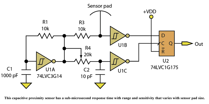
Three devices in a quad Schmitt Trigger and a Flip-Flop create a simple yet sensitive proximity sensor. The described circuit utilizes three devices from a quad Schmitt Trigger configuration alongside a Flip-Flop to construct a proximity sensor. The Schmitt Trigger...