
digital to analog

This circuit functions as a Digital-to-Analog Converter (DAC) that translates digital signals into corresponding analog voltages, making it ideal for applications requiring precise control. The microcontroller sends an 8-bit binary value to the circuit, which is then interpreted by the resistor ladder network. The ladder is designed to divide the reference voltage into discrete steps, allowing for a linear output that corresponds to the binary input.
The OP07 operational amplifier is employed to buffer the output from the resistor ladder, ensuring that the output voltage remains stable and is not affected by the load. With an offset error of just 70 µV, the OP07 provides high accuracy in the voltage output, which is crucial for applications where precision is required.
The 74HCT373 latch plays a key role in stabilizing the output. By latching the input data, it ensures that the analog output remains constant even if the microcontroller's output changes. This is particularly useful in control systems where a stable reference voltage is necessary for actuators or other components.
The LM336 voltage reference is used to provide a stable power supply to the circuit, which is essential for maintaining the accuracy of the DAC. The combination of the stable reference, precise resistor ladder, and low-offset operational amplifier results in a highly reliable DAC solution. When the input data from the counter changes, the output will exhibit a staircase waveform, reflecting the incremental changes in the digital input. This behavior is beneficial in applications such as signal generation, where a smooth transition between voltage levels is required.
In summary, this circuit effectively converts digital signals to analog voltages with high precision, making it suitable for various control and automation applications.This can be used to convert a byte sent from a microcontroller to a analog value like say 1. 51 V. At full scale, when all 8 bits are high calibrate to give 2. 55 V then ever bit increment is 0. 01V, 10mV steps. If the eight bits inputs are from a counter you then will see a staircase waveform at output, each step being 10mV higher or lower depending on whether the counter is counting up or down. The accuracy of the analog output depends on the resistor ladder. The OP07 has an offset error of about 70uV only. The 74HCT373 power is derived from LM336 a stable reference so that the D-A is accurate. The 8 bit data can be latched with the 74HCT373 to get a stable analog value for control systems. 🔗 External reference
Related Circuits
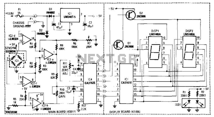
A bridge circuit is utilized to generate a signal from the output of vacuum sensor IC1. IC2b introduces an approximate 0.2 V offset for IC4, the A/D converter. IC2b and IC2d function as voltage followers that drive the differential...
The MCU is an ATMEL 89C4051 CMOS Microcontroller featuring 4kB of code memory, 128 bytes of on-chip RAM, and 8-bit Port1 and Port3. The A/D chip is a HARRIS CA3162, which functions as a 3-digit digital voltmeter (DVM). This...
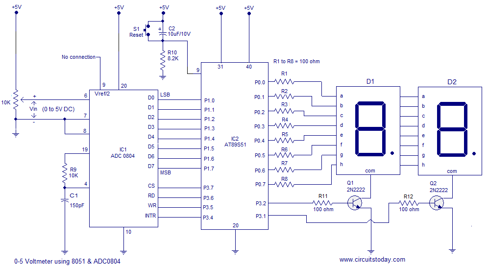
A simple 0-5 digital voltmeter utilizing the 8051 (AT89S51 microcontroller) is presented, accompanied by a circuit diagram and assembly language (ASM) code. This digital voltmeter is designed for straightforward voltage measurement. The circuit employs an AT89S51 microcontroller, which serves as...
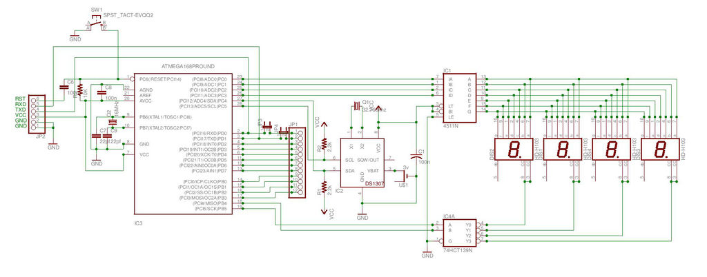
This is the second instructable focused on creating a digital watch as a learning experience. An Atmega644 chip from a Sanguino was available, which would have sufficed, but the intention was to burn an Arduino bootloader and test its...
A basic digital voltmeter circuit utilizing the Harris Semiconductor ICL7107 is presented. It operates within a 2-V range. Calibration involves applying a known voltage of 1.2 V to the input and adjusting resistor R3 to achieve an accurate reading...
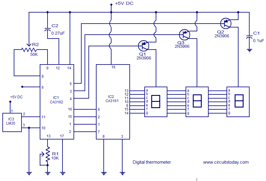
A simple digital thermometer circuit without a microcontroller and featuring a seven-segment LED readout is presented. The circuit utilizes three integrated circuits (ICs): CA3162, CA3161, and LM35. The CA3162 is a monolithic analog-to-digital (A/D) converter with a BCD output....