
Piezo Buzzer driver

The basic buzzer driver circuit is designed to generate an audible tone by driving a piezoelectric buzzer. The circuit operates effectively within a voltage range of 3 to 28 volts DC, making it versatile for various applications, including alarms, notifications, and signaling devices. The output sound pressure level of 85 dBA at the resonance frequency of approximately 5 kHz ensures that the buzzer is loud enough for most environments.
The core components of the circuit typically include a transistor, which acts as a switch to control the power delivered to the buzzer. When a control signal is applied to the base of the transistor, it allows current to flow from the collector to the emitter, energizing the buzzer. The choice of transistor must accommodate the required current of 6 mA and the voltage range specified.
To achieve the desired resonance frequency, the circuit may incorporate passive components such as resistors and capacitors. These components can be arranged in an oscillator configuration to produce a square wave signal, which is essential for driving the piezoelectric buzzer at its optimal frequency. The selection of the capacitor value will influence the frequency of oscillation, enabling fine-tuning of the output tone.
In summary, this buzzer driver circuit is a straightforward yet effective solution for generating audible alerts, leveraging a combination of transistors and passive components to achieve the desired frequency and sound output. The design's flexibility in voltage operation makes it suitable for a wide range of electronic projects.This is a basic Buzzer driver circuit with resonance frequncy approximatly 5 Khz, 85 dBA. It operates on 3 to 28 v DC at 6mA. 🔗 External reference
Related Circuits
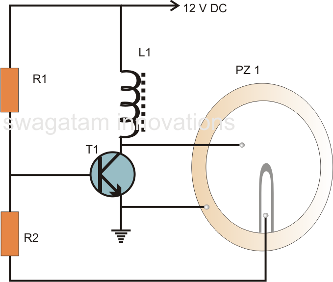
A very simple piezoelectric buzzer can be constructed with minimal electronic components, requiring just a single transistor, a coil, and a piezo buzzer to produce a sound that may be quite piercing. This buzzer circuit operates in a unique...

This circuit design for a laser diode driver can be implemented using a voltage-controlled current source. This simple linear laser diode driver provides a cleaner drive current compared to switched (PWM) drivers. The circuit is based on the OPA350...
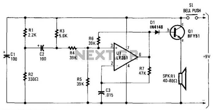
When the switch SI is pressed, a positive voltage is applied to capacitor C2 and the non-inverting terminal of operational amplifier U1. The circuit oscillates at a low frequency initially. As capacitor C2 charges through resistor R3, there is...
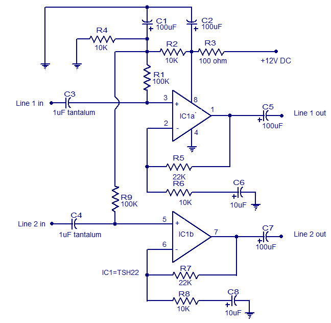
This is the circuit diagram of a two-channel audio line driver utilizing the high-performance dual op-amp IC TSH22 from ST Microelectronics. The IC features a 25 MHz bandwidth, low distortion, and high output current, enabling it to drive medium...
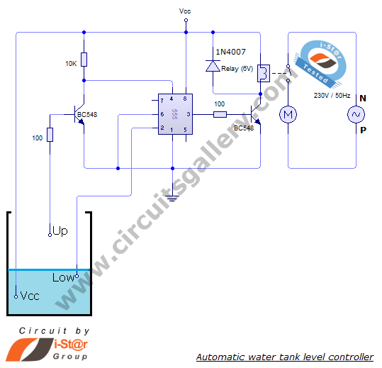
The automatic water level controller circuit is a straightforward engineering project that can automatically switch a domestic water pump on and off based on the water level in a tank. This motor driver circuit can be implemented at home...
This design was created to address a challenge with the tailwheel doors of the P-51 Mustang. The issue arises from the complex undercarriage sequence, which would necessitate two independent sequencers. The closing sequence involves the main gear doors opening,...