
Piezoelectric Alarm Circuit

A CDS photo cell, constructed from cadmium sulfide, is a semiconductor that alters its resistance in response to light exposure. The greater the light intensity, the lower the resistance. This low resistance allows positive voltage to flow to the base of the PNP transistor Q1, keeping it turned off while light is incident on the CDS cell. Once the light is removed, the CDS cell's resistance exceeds 100 kΩ, which triggers Q1 to turn on. This action enables positive voltage to reach the emitter lead of Q2, initiating oscillation and causing the piezoelectric element (transducer) to generate a loud signal.
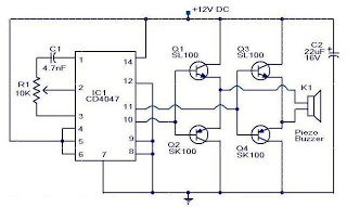
The circuit operates on a simple principle of light detection and sound generation. The CDS cell serves as a light sensor, influencing the state of transistor Q1, which in turn controls the oscillation of transistor Q2. This oscillation is crucial for driving the piezoelectric buzzer, which operates at a frequency of 3.137 kHz, producing a high-pitched sound that serves as the alarm signal. The design efficiently combines light-sensing and sound-generating components into a compact circuit, making it suitable for various applications where light presence detection is essential. The choice of a piezoelectric buzzer ensures that the alarm is both loud and effective, while the use of transistors allows for reliable switching and amplification of the signal. Overall, this circuit exemplifies a straightforward yet effective approach to creating an alarm system based on light detection. The alarm uses a fixed-frequency piezoelectric buzzer in conjunction with the cadmium-sulfide (CDS) cell and the two-transistor circuit to provide a unique effect. Whenever light reaches the CDS photo-electric cell, the alarm is silent. But when no light strikes the cell, transistor Ql turns on, and the circuit emits a high-pitched tone.The alarm consists of a piezoelectric disk that oscillates at the fixed frequency of 3.137 kHz, created by transistor Q2, capacitor CI and C2, and resistors Rl through R3.
Transistor Ql is used as a switch. It is forward-biased on by R4;-however, the CDS coll turns Ql off when the light is striking it. A CDS photo cell is made from cadmium sulfide, a semiconductor material that changes resistance when the light strikes it. The greater the amount of light, the lower the resistance. The low resistance conducts positive voltage to the base of pnp transistor Ql, keeping it turned off` when the light shines on the CDS cell.
As soon as the light is removed, the CDS cell provides a resistance of over 100 kQ. That causes Ql to turn on, allowing a positive voltage to reach the emitter lead of Q2, which then begins to oscillate. That then causes the piezoelectric element (transducer) to produce a loud signal.
Related Circuits
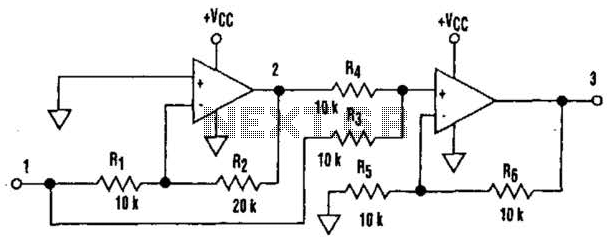
It is well understood that utilizing single-supply operational amplifiers (op amps) can present challenges when implementing simple functions in a bipolar signal environment. Often, this necessitates the use of additional op amps and other electronic components. Considering this, it...
Figure A illustrates the schematic of a microstrip single-stage RF amplifier. This amplifier utilizes the M/A-Com LF2810A MOSFET, which is rated for 10 watts and operates at 28 volts, but it delivers sufficient gain for this application at a...
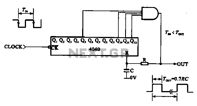
This document illustrates the application of a CMOS integrated circuit (IC) count divider, specifically the TC4040, which functions as a 12- or 14-bit counter. The circuit can be configured to achieve various frequency division ratios, such as a 1:3600...
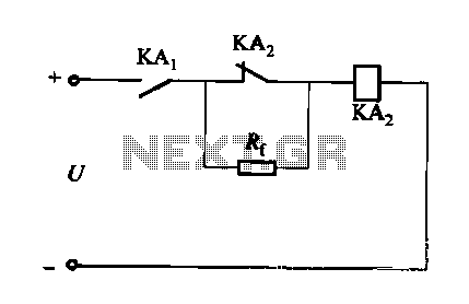
A DC relay or contactor is utilized to enhance the excitation pull-in and release mechanisms in a circuit. The relay circuit, as depicted in Figure 6-28, facilitates improved return line efficiency. When the control relay KAi is activated, its...
This is a small circuit designed as an insect repellent, targeting mosquitoes and birds by producing high-frequency audio signals. These signals interfere with the hearing of insects, making it unbearable for them, causing them to flee. The operation of...
Active power factor correction stabilizes the electrical demand of a device to provide optimal power factor characteristics for various types of loads. To comply with power factor regulations, a cost-effective solution should be designed. In many applications, the requirement...