
pippin qrp transmitter

The circuit utilizes a Colpitts oscillator configuration, characterized by its use of a crystal for frequency stability. The oscillator consists of a tank circuit made from a combination of capacitors and an inductor, which helps define the oscillation frequency. The output is taken from the collector of the transistor, which is coupled to the base of the PNP transistor. This direct coupling allows for a straightforward design, minimizing component count and complexity.
In operation, the PA stage is designed to amplify the oscillator's output. The small forward bias generated by the oscillator ensures that the PA stage is in a ready state without drawing significant current when idle. This design choice enhances the overall efficiency of the circuit by reducing power consumption during non-active periods.
Keying the circuit is achieved through the emitter of the oscillator stage, providing a simple means to control the output signal. When the key is released, the lack of current flow ensures that the PA remains off, preventing unwanted power draw and heat generation. This feature is particularly beneficial in applications where power conservation is critical.
The design's isolation of the PA stage from the oscillator is a notable advantage, as it maintains the integrity of the oscillator's frequency. The low-value collector load resistor minimizes the interaction between the oscillator and the PA, allowing for stable operation even under varying load conditions. The circuit's resilience to load changes, such as a brief short to ground, demonstrates its robustness and reliability.
The PA stage's specifications indicate it operates efficiently at a current of 120 to 150 mA with a supply voltage between 12 and 14 volts. The output power of over 1 watt into a 50-ohm load at a frequency of 7 MHz suggests that the circuit is well-suited for applications requiring moderate power levels, such as in amateur radio or other RF transmission scenarios.
Thermal management is addressed through the implementation of a "Stove Pipe" heat sink on the PA transistor, which effectively dissipates heat generated during operation. The ability to run continuously for extended periods without overheating is a testament to the design's effectiveness and reliability in practical applications. Overall, this Colpitts oscillator and PA circuit combination presents a simplified yet highly functional solution for RF amplification needs.Basically, it is a conventional Colpitt type crystal oscillator but with the output taken from a low value collector load resistor and direct coupling is made into the base of the PNP device used as an amplifier. The result is a circuit even more simple than the OXO and with considerable advantages. The small amount of forward bias developed for t he PA stage makes it very much easier to drive but is less than the voltage required to actually bias the stage "ON". Keying is in the emitter circuit of the oscillator stage and when the key is up and no current is being drawn there is no forward bias at all on the PA stages.
The isolation of the PA from the oscillator by taking the drive from the low value oscillator collector load, is most impressive and there is virtually no pulling of the oscillator even if the PA load is briefly shorted to ground. Input to the PA stage runs at 120 to 150mA. at 12 to 14 volts and output on 7Mhz runs at better than 1 watt measured into a 50 ohm load. The PA transistor has a "Stove Pipe" heat sink attached and has been left running continously for more than 1 hour without any complaint from the PA stage.
🔗 External reference
Related Circuits

The ordinary triode 3DA87C is utilized to create a long-range FM transmitter circuit, which functions as a standard three-point oscillator circuit. This remote transmitter circuit is capable of large current emissions, achieving a range of up to 1 kilometer...
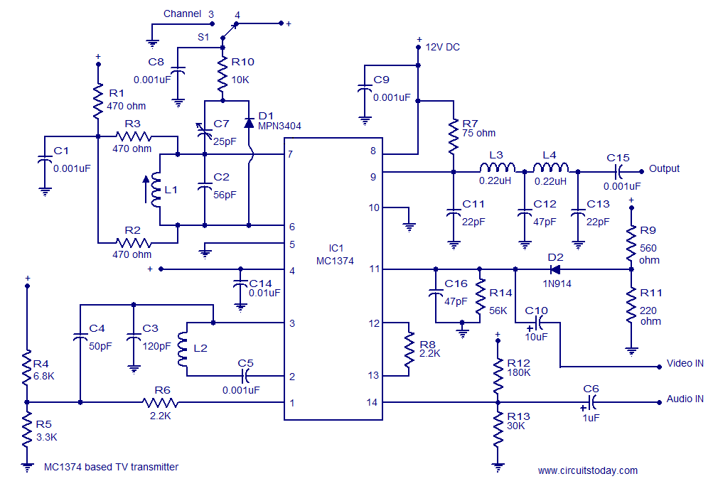
A simple TV transmitter circuit utilizing the TV modulator circuit IC MC1374. It operates with a 12V supply and is capable of broadcasting on channel 3 or 4, employing FM modulation for sound transmission. The TV transmitter circuit based on...
Small Radio Transmitter. This article contains information about building a small radio transmitter, which has a PCB measuring 1.75 x 2.5 inches (45 mm x 68 mm) and offers a range of approximately 30 yards. The small radio transmitter is...
This compact video transmitter is highly useful for video surveillance over short distances (up to 100 meters) and is equipped with either a black and white or infrared camera module. The compact video transmitter is designed for efficient video surveillance...

The TV transmitter described utilizes UK standard 1 FM modulation for sound and PAL modulation for video. The audio signal to be modulated is first amplified using transistor Q1 and its associated components. Transistor Q2 serves dual functions: generating...

A high-quality FM stereo transmitter circuit schematic utilizing the BA1404 FM transmitter integrated circuit (IC). This circuit is straightforward to assemble, requiring only a few external components. The FM stereo transmitter circuit based on the BA1404 IC is designed to...