
fm stereo transmitter

The FM stereo transmitter circuit based on the BA1404 IC is designed to provide a reliable and efficient means of broadcasting audio signals over FM radio frequencies. The BA1404 is a versatile transmitter IC that integrates several functions, including modulation and frequency generation, making it an ideal choice for simple FM transmitter applications.
The circuit typically consists of the BA1404 IC, a few passive components such as resistors and capacitors, and an external antenna for signal transmission. The power supply for the circuit can be derived from a standard battery or DC power source, ensuring portability and ease of use.
Key components of the circuit include:
1. **BA1404 IC**: This is the heart of the transmitter, responsible for modulating the audio input and generating the FM signal. It operates within a specified voltage range, typically around 3V to 12V, and can accommodate various audio input levels.
2. **Audio Input**: The circuit can accept audio signals from various sources, such as microphones, audio players, or other audio devices. An audio coupling capacitor may be used to block DC components while allowing AC audio signals to pass through.
3. **Resistors and Capacitors**: These components are used to set the operating frequency of the transmitter and to filter signals to ensure clear audio quality. The values of these components can be adjusted to modify the frequency response and transmission range.
4. **Antenna**: A simple wire antenna can be connected to the output of the BA1404 to radiate the FM signal. The length of the antenna should be tuned to the desired transmission frequency for optimal performance.
5. **Power Supply**: The circuit requires a stable power supply to function correctly. A battery pack or a regulated DC power source can be used to power the transmitter.
The construction of this circuit is relatively simple, making it suitable for hobbyists and students interested in exploring FM transmission technology. Proper attention must be given to component placement and soldering techniques to ensure reliable operation. Additionally, adherence to local regulations regarding FM transmission power and frequency usage is essential to avoid interference with licensed broadcasts.A good quality FM stereo transmitter circuit schematic using ba1404 fm transmitter IC. Easy to build circuit with only few external parts.. 🔗 External reference
Related Circuits
Many times we needed to use a simple circuit of preamplifier, with few components and facility of made. This circuit uses an opamp, the Motorola, TCA5550, that contains a double amplifier, as outputs for the adjust of volume, balance,...
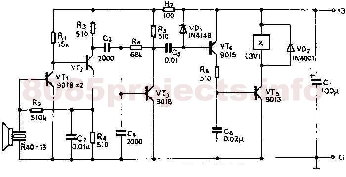
A 40kHz ultrasonic transmitter circuit consists of three oscillators (F1, F2, and F3), with F3 generating a 40kHz square wave output. The frequency is primarily determined by components C1, R1, and an adjustable resistor (RP). The excitation output from...
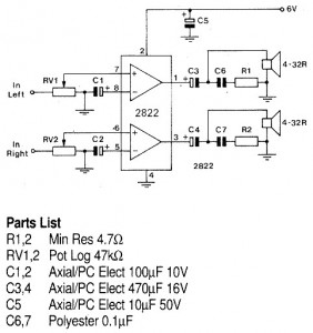
A 1W stereo headphone amplifier circuit, based on the TDA2822, is designed for portable players, radios, and other electronic devices that utilize headphones as the output. The TDA2822 is a dual audio power amplifier IC capable of delivering up to...
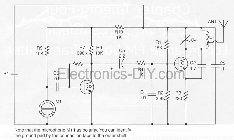
This document presents a Long Range FM Transmitter circuit, which is a highly sensitive, low-power FM transmitter. It includes a radio frequency (RF) oscillator section connected to a high-sensitivity, wide pass-band audio amplifier and a capacitance microphone equipped with...
The circuit is basically a radio frequency (RF) oscillator that operates around 100 MHz. Audio picked up and amplified by the electret microphone is fed into the audio amplifier stage built around the first transistor. Output from the collector...
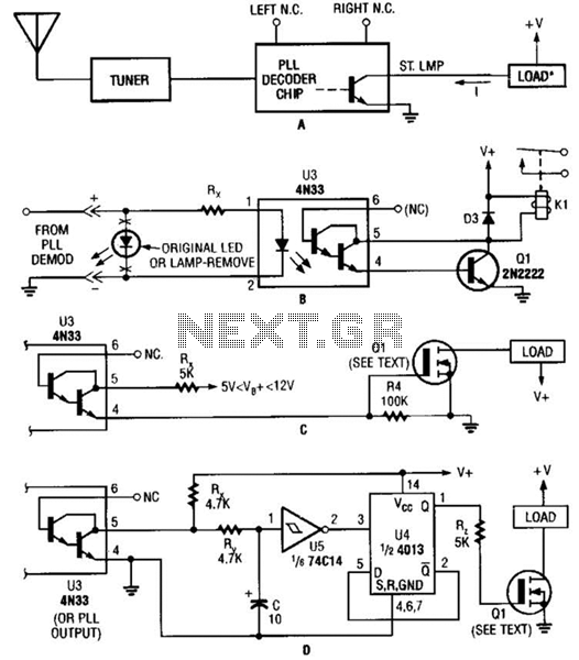
Several possible interface circuits are presented for use with a remote-control transmitter. The circuit labeled A demonstrates a typical FM stereo MUX decoder with a load connected directly to the open-collector output of a TA7343 PLL. The circuit labeled...