
Plant Moisture MeterCircuit Based On The LM741 IC

The Plant Moisture Meter Circuit utilizes the LM741 operational amplifier to measure the moisture content in soil. The circuit typically includes a pair of probes inserted into the soil, which serve as the moisture sensors. When moisture is present, the resistance between the probes decreases, allowing a small current to flow. This current is then amplified by the LM741, which is configured as a non-inverting amplifier.
The output from the LM741 is connected to a meter, such as a galvanometer or a digital voltmeter, which visually indicates the moisture level. The scale of the meter can be calibrated to provide specific readings, allowing users to assess whether the soil is adequately moist for plant growth.
Additional components may include a potentiometer for adjusting the sensitivity of the circuit, ensuring accurate readings across different soil types. Power supply considerations should also be made, as the LM741 typically operates within a voltage range of ±15V, which should be supplied to the circuit for optimal performance.
Overall, this circuit serves as a practical tool for gardeners and agricultural professionals to monitor soil moisture, promoting better plant care and resource management.The following circuit shows about Plant Moisture Meter Circuit Diagram. This circuit based on the LM741 IC. Features: meter indicate whether it is .. 🔗 External reference
Related Circuits
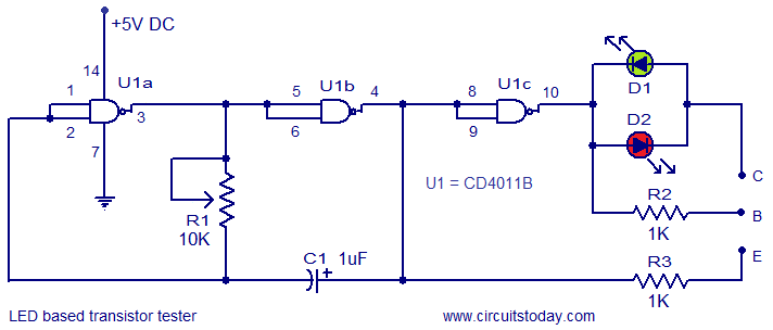
This circuit represents a simple transistor tester that utilizes two LEDs to indicate the condition of a transistor. It is capable of testing both PNP and NPN transistors. The core component of the circuit is the quad 2-input CMOS...
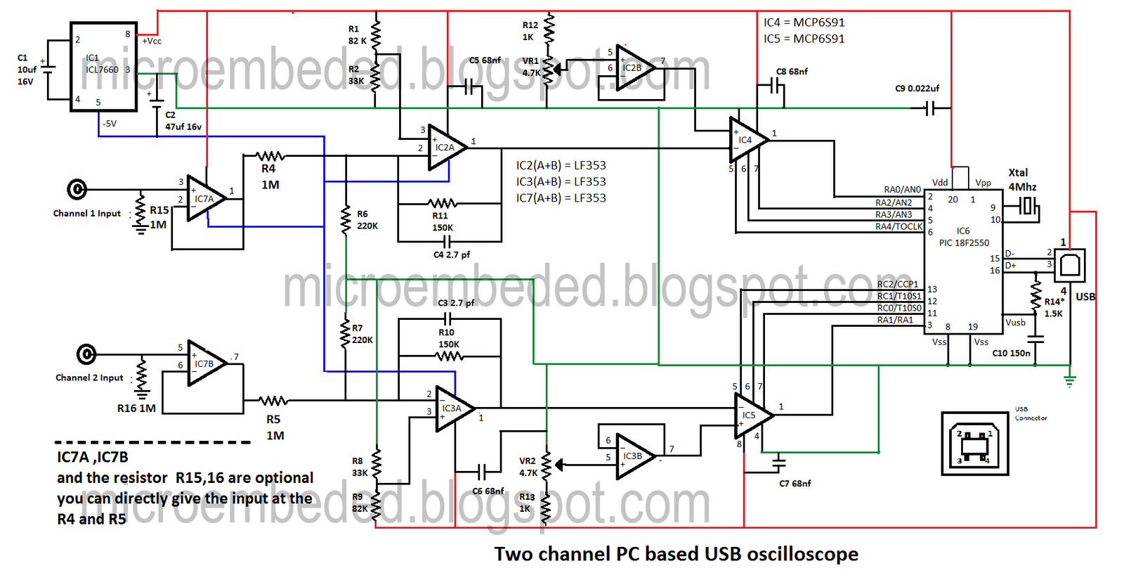
Portable PCs are now common, and a USB connection is a more effective solution. This document presents an oscilloscope that utilizes the USB port of a PC, operating at frequencies up to 10 kHz with an input voltage range...
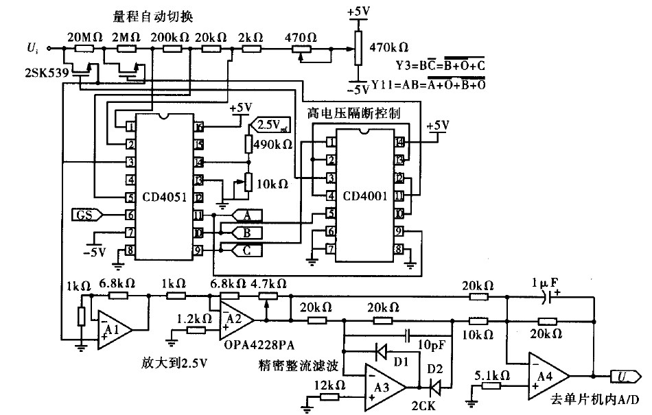
Voltage measurement is a fundamental aspect of electronic technology today, with increasing demands for accuracy and functionality in instruments. This is particularly critical when measuring signals with significant phase differences, as it is essential to ensure the accuracy of...
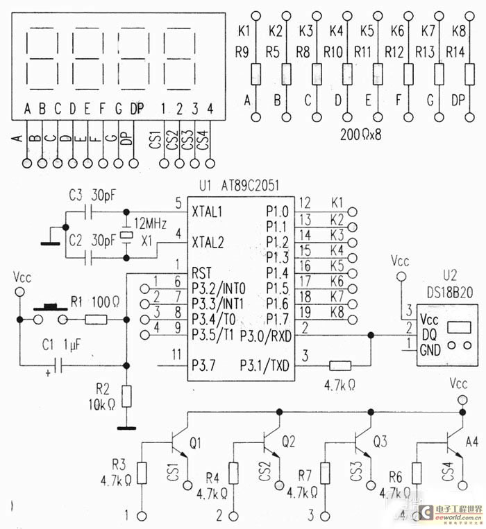
This project utilizes a USB port for power supply, employs a DS18B20 temperature sensor for data acquisition, and is controlled by an AT89C2051 microcontroller. A common anode quad-digit seven-segment display is used for output, allowing for temperature measurement visualization....
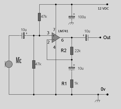
This circuit is an Op-Amp Microphone Preamplifier that operates using a single power supply. It is suitable for both dynamic and electret microphones. The schematic illustrates the configuration with a dynamic microphone; however, for electret microphones, a pair of...
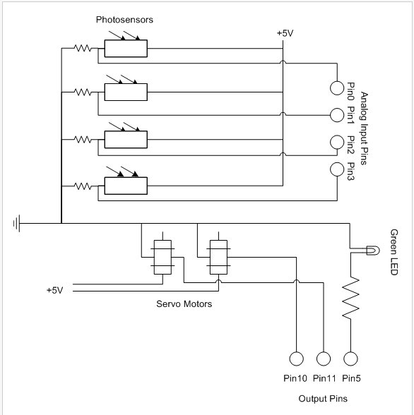
The PhytoBot is a semi-intelligent plant that reacts to external stimuli, specifically light intensity and light location, mimicking the behavior of a phototropic plant. It is designed as an interactive artwork intended for prolonged operation. The motivation behind this...