
Two-Channel PC Based Oscilloscope USB

This USB-based oscilloscope design presents a compact solution for users requiring an efficient and effective means of capturing and analyzing signals. The integration of the PIC18F2550 microcontroller ensures seamless communication with the PC while managing the analog signal processing through the MCP6S91 gain amplifiers. The use of voltage-shifting amplifiers allows for the adaptation of higher input voltages to a suitable range for the microcontroller, enhancing the oscilloscope's versatility. The design also incorporates robust data transmission capabilities, allowing for high-speed communication and accurate signal representation. Overall, this oscilloscope serves as a practical tool for professionals and hobbyists alike, offering advanced features in a user-friendly format.Since portable PCs are today common and a USB linkis a better solution here we present an oscilloscope using USB port of the PC that operates at upto 10 kHz with ±16V input voltage. Ithas much more improved features thanthe PC-based oscilloscope.The oscilloscopeuses IC PIC18F2550 from Microchipas the main controller, which makesthe oscilloscope
compact as there is noneed of additional power supply forthe entire circuit board. At the heart of this oscilloscope is USB2. 0-compliant microcontroller PIC18F2550 from Microchip. You can also use IC18F2445 in place of PIC18F2550. Specifications of this microcontroller are:- avobe figrue shows the circuit of the two-channel PC-based oscilloscope. MCP6S91 from Microchip Technology is an analogue programmable gain amplifier that is well suited to driving analogue-to-digital converters (ADCs) and an analogue input to a PIC microcontroller.
Two MCP6S91 programmable gain amplifiers (IC4 and IC5) make it possible to choose the input ranges for each of the two channels, by selecting a gain from 1:1 to 32:1. The amplifiers are small, cheap and easy to use. A simple three-wire serial peripheral interface (SPI) allows the PIC to control them through pins 5, 6 and 7.
The MCP6S91 amplifier is designed with CMOS input devices. It is designed to not exhibit phase inversion when the input pins exceed the supply voltages. The maximum voltage that can be applied to the input pin is 0. 3V (VSS) to +0. 3V (VDD). Input voltages that exceed this absolute maximum rating can cause excessive current into or out of the input pins. Current beyond ±2 mA can cause reliability problems. Applications that exceed this rating must be externally limited with a resistor to the input pin. (pin 3), which is an analogue input, should be at a voltage between VSS and VDD. The voltage at this pin shifts the output voltage. The SPI interface inputs are chip-select (CS), serial input (SI) and serial clock (SCK). These are Schmitt-triggered, CMOS logic inputs. The only disadvantage is that these amplifiers accept only positive signals. That`s why voltage-shifting amplifiers LF353 (IC2A and IC3A) are used, one each for each channel input (see Fig.
1). The LF353 is a JFET input operational amplifier with an internally compensated input offset voltage. The JFET input device provides wide bandwidth, low input bias currents and offset currents. This voltage-shifting amplifier results in a high input impedanceand an attenuation factor of 1:4. 5. A ±16V input signal is then shifted to the0-5V range when the programmed gain is 1:1. Two halves of the LF353 (IC2B and IC3B) are used as voltage followers to provide a low-impedance shifting voltage (Vref) to the programmable amplifiers. This voltage must be precisely adjusted with two 4. 7-kiloohm presets to measure precisely 2. 5V level on the inputs of IC2 and IC3 when the input signals are grounded. Because LF353 opamps need a symmetrical supply voltage, a small DC-DC voltage converter ICL7660 (IC1) is used to feed 5V to LF353.
With its small 8-pin DIP package, it needs only two polarised capacitors. ICL7660 can be replaced with a MAX1044. The MAX1044 and ICL7660 are monolithic, CMOS switched-capacitor voltage converters that invert, double, divide or multiply a positive input voltage. These are pin compatible with the industry-standard LTC1044 All the data is transmitted on the D+/D- symmetrical pins using a variable bit rate.
The position of a resistor (R13) on D+ or D- allows you to choose between the full-speed (12 Mbps) and lowspeed modes (1. 5 Mbps). Note that the IC18F2550/2455 devices have built-in pull-up resistors designed to meet the requirements of low-speed and fullspeed speed USB.
The UPUEN bit (UCFG=4) enables the internal pull-ups. In this project, R13 is not used. External pullup may also be used. The VUSB 🔗 External reference
Related Circuits
PIC C Compilers are utilized to compile source code, leveraging the extensive built-in functions offered by these compilers. A single C statement can produce multiple pages of PIC RISC instructions, eliminating the need for manual coding. CCS charges $125...
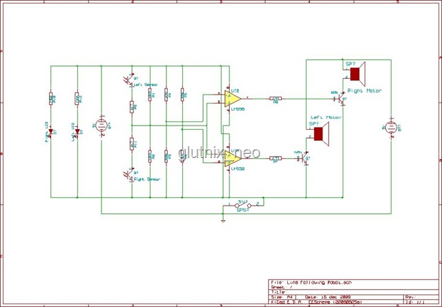
The original FLED-based SE uses a flashing LED to drive a type 1 solar engine (you'll note that it's just like the Zener-based SE, but with a FLED in the starring role). The good news is that all the...
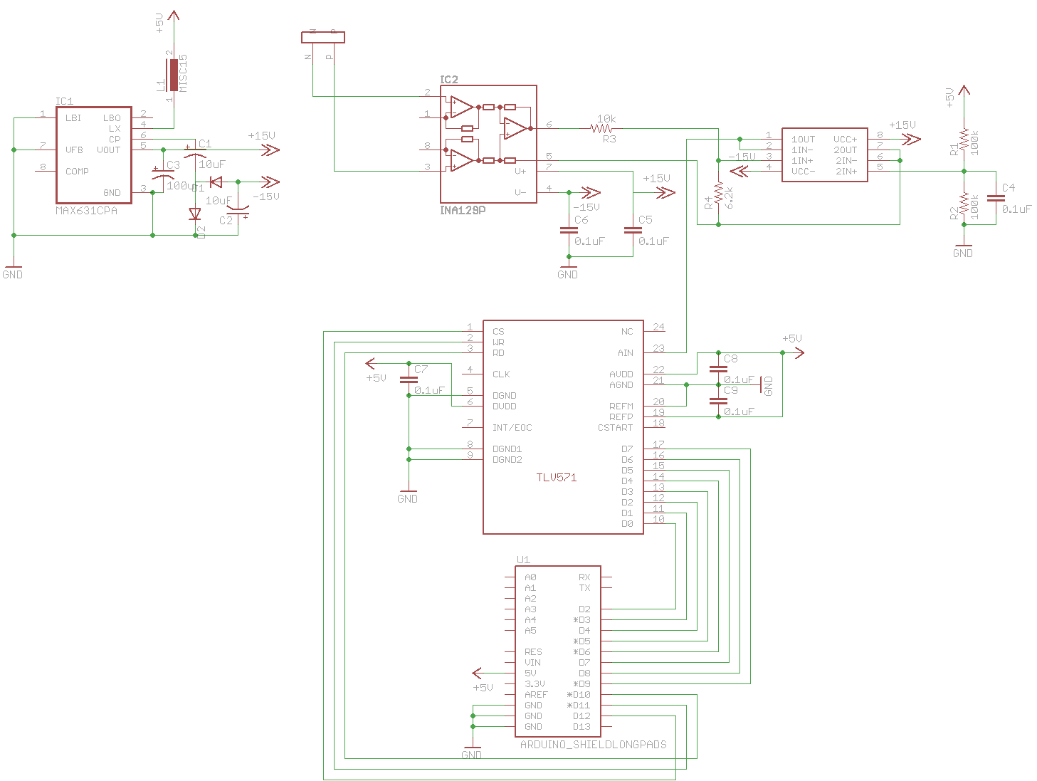
A digital oscilloscope is being developed using Arduino, designed as an Arduino Shield. The current implementation functions but exhibits signal distortions. A TLV571 chip is utilized in the design. The project involves creating a digital oscilloscope that can be mounted...
Numerous effective In-System Programming (ISP) designs are available for 8-bit AVR microcontrollers. However, many of these designs necessitate a pre-programmed microcontroller, presenting the "Chicken or Egg" dilemma: programming microcontrollers requires having one that is already programmed. While solutions utilizing...
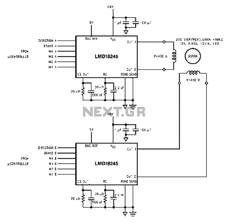
An innovative current detection method eliminates the power loss associated with the sense resistor in series with the motor. A 4-digit analog converter (DAC) facilitates digital control of the motor current path, simplifying the implementation of full, half, and...
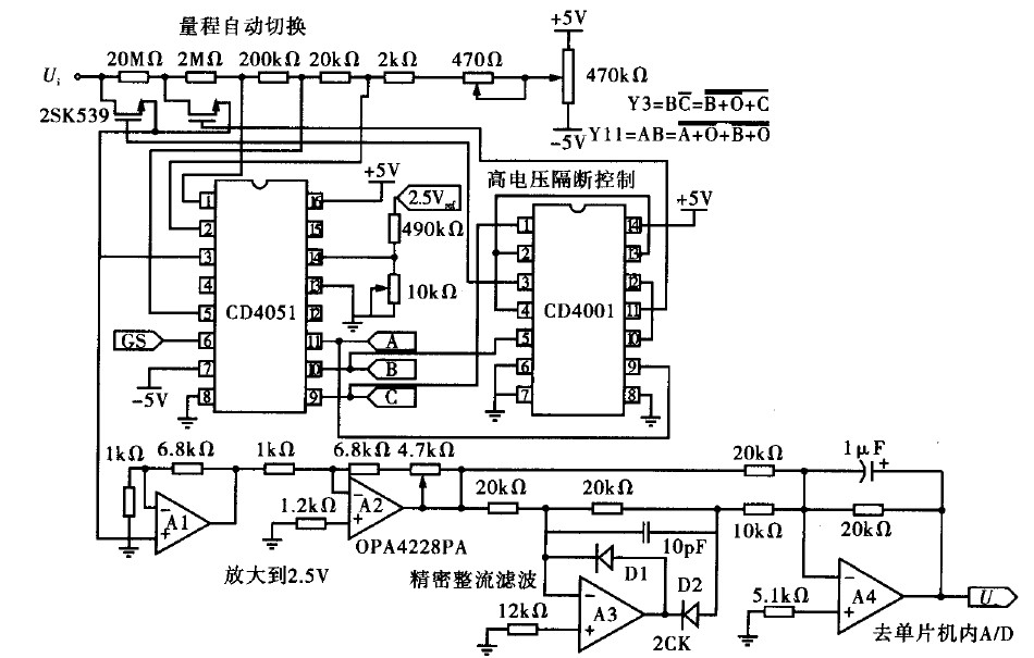
Voltage measurement is a fundamental aspect of electronic technology today, with increasing demands for accuracy and functionality in instruments. This is particularly critical when measuring signals with significant phase differences, as it is essential to ensure the accuracy of...