
Plant Watering Watcher Circuit Schematic

The circuit utilizes a moisture sensor that detects the water content in the soil. When the soil moisture drops below a predetermined threshold, the sensor triggers a comparator circuit. This comparator is typically configured with a reference voltage that corresponds to the desired moisture level. The output of the comparator is connected to a microcontroller or a simple transistor switch that controls the LED.
In this setup, the LED serves as a visual indicator of the soil's moisture condition. The blinking rate of the LED can be influenced by the design of the timing circuit, which may include components like capacitors and additional resistors. The adjustment of R2 allows for fine-tuning of the sensitivity, ensuring that the circuit can effectively respond to different environmental conditions and soil compositions.
For optimal performance, the moisture sensor should be positioned at an appropriate depth within the soil, ensuring accurate readings. The circuit may also benefit from additional features such as a power-saving mode to prolong battery life or the incorporation of a buzzer for audible alerts. Overall, this moisture-sensing circuit is a practical solution for plant care, providing timely notifications to users regarding the watering needs of their plants.This circuit is intended to signal when a plant needs water. A LED flashes at a low rate when the ground in the flower-pot is too dry, turning off when the moisture level is increasing. Adjusting R2 will allow the user to adapt the sensitivity of the circuit for different grounds, pots and probe types
🔗 External reference
Related Circuits
There is a modification to the RC delay circuits that some may want to consider. If a shorter discharge time is desired, this modification enables the circuit to restart more quickly. The modification to the RC delay circuit involves adjusting...
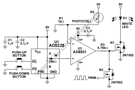
The following circuit illustrates the AD8531 integrated circuit used for the automatic control of LCD panel backlighting. Features include the ability to compensate for aging effects and other functionalities. The AD8531 is a precision operational amplifier known for its low...
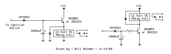
The two circuits di atas illustrate opening a relay contact a short time after the ignition or light switch is turned off. The capacitor is charged and the relay is closed when the voltage at the diode anode rises...
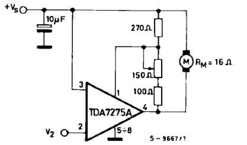
The TDA7275A linear integrated circuit, housed in a minidip plastic package, can be utilized to design a straightforward speed regulator electronic project suitable for regulating the speed of small DC motors. The TDA7275A DC speed controller project is specifically...
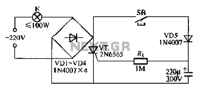
This circuit is a simple connection delay lamp circuit. When the lights are turned on and the switch is pressed, the power supply is activated. The capacitor charges rapidly, causing the thyristor (VT) to open, which in turn lights...
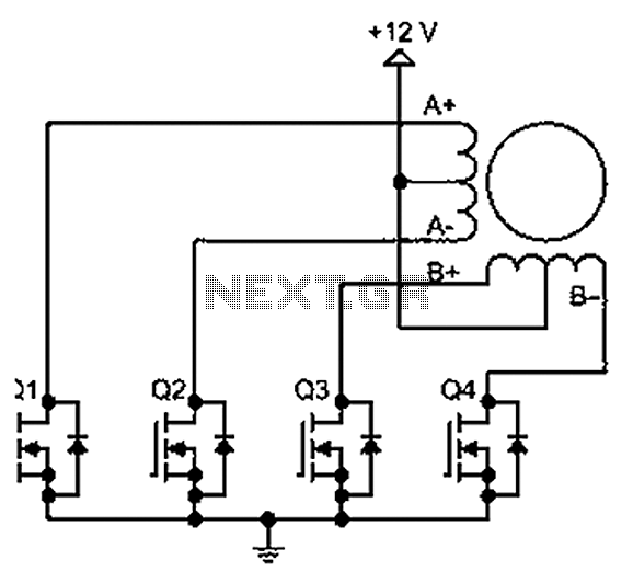
A bipolar stepper motor drive circuit is presented, utilizing eight transistors to operate two phases. This bipolar drive circuit can accommodate both four-wire and six-wire stepper motors; however, it is primarily designed for four-wire bipolar configurations, which can significantly...