
Plant Watering Watcher Circuit Schematic

This circuit operates on a 3V power supply, which can be provided by two AA batteries in series or a similar voltage source. The core of the circuit includes a microcontroller or a simple timer IC, such as the 555 timer, configured in astable mode to generate a square wave output. This output drives a light-emitting diode (LED), which flashes at regular intervals to alert the user that the plant requires watering.
The circuit can be enhanced by incorporating a soil moisture sensor. This sensor monitors the moisture level in the soil and provides feedback to the microcontroller. When the moisture level falls below a predefined threshold, the microcontroller activates the LED, causing it to flash. This feedback loop ensures that the LED only signals when the plant truly needs water, thereby conserving battery life and preventing over-watering.
A resistor in series with the LED limits the current to prevent damage to the LED. Additionally, a capacitor may be used in conjunction with the timer IC to set the flashing frequency of the LED. The values of the resistor and capacitor can be adjusted to customize the flashing rate according to user preferences.
For added functionality, a buzzer or an additional alert mechanism can be integrated into the circuit. This would provide an audible signal in conjunction with the visual LED indication, making it easier for the user to recognize when the plant needs water, especially from a distance.
Overall, this circuit is a practical solution for plant care, combining simple electronics with effective monitoring to support healthy plant growth.A flashing LED signals the necessity to water a plant, 3V powered circuit This circuit is intended to signal when a plant needs water. A LED flashes at a.. 🔗 External reference
Related Circuits
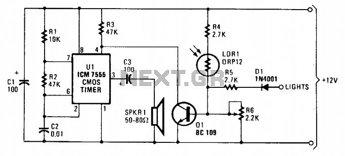
As dusk begins to fall, the sensor, which is a cadmium-sulfide light-dependent resistor (LDR), activates a small horn to provide an audible reminder to turn on the lights. The circuit can be turned off by simply switching on the...
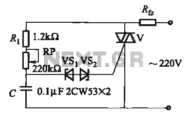
The introduction for a unidirectional thyristor trigger circuit is also applicable to the TRIAC. Several bidirectional circuits are illustrated in Figure 16-28. Figures 16-28 (a) and (b) depict a direct trigger circuit; Figure 16-28 (c) illustrates a dual diode...

One section of the precision audio frequency generator utilizes an electret microphone element to capture audio from the piano. The captured signal is processed and transmitted to one channel of a dual-trace oscilloscope. The other section of the circuit...

The speed of the display can be adjusted as desired. The output from the 555 timer is directly connected to the input of a CD4017 decade counter. The input of the counter is referred to as the CLOCK line...
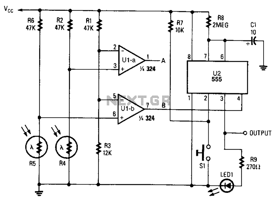
A combined monostable multivibrator using the 555 timer integrated circuit, along with a pair of light control comparators. This circuit can be utilized to control a load based on the timing parameters set within the circuit. The circuit comprises a...

A brief history: Like many tutorials, this one begins with a historical overview. However, it must be noted that there is limited background information available regarding the development of 7-segment displays. 7-segment displays are widely used electronic components that...