
Monostable circuit diagram of a light control

The circuit comprises a 555 timer configured in monostable mode, which generates a single output pulse in response to a triggering input. The duration of this pulse is determined by external resistors and capacitors connected to the timer. A pair of light control comparators are integrated into the design to monitor ambient light levels. These comparators provide the necessary feedback to the 555 timer, enabling or disabling its output based on the light conditions.
During daylight hours, the operation of the timer (U2) is disabled, ensuring that no output is generated. This prevents unnecessary power consumption by the load when ambient light is sufficient. As the light levels drop, the comparators detect the change and trigger the 555 timer, allowing it to produce an output pulse. The output can then be used to activate a load, such as a light fixture, ensuring that it operates only when required, thereby enhancing energy efficiency.
The circuit design allows for adjustable timing intervals, which can be fine-tuned by varying the resistor and capacitor values. This flexibility makes the circuit suitable for a variety of applications, including outdoor lighting systems, automatic night lights, and other scenarios where light level control is desired. The integration of the 555 timer with light control comparators provides a robust solution for automated load management based on environmental conditions. Combined monostable multivibrator 555 and a pair of light control and light control comparator monostable phase. Depending on the time of the circuit can be used to enable load device operation. During the day, the timer U2, is disabled, it does not produce any output. It produces no output.
Related Circuits

This compact circuit is capable of distinguishing between light and darkness, making it highly beneficial for controlling the operation of signs, porch lights, or other devices in response to changing light conditions. The circuit operates using a light-dependent resistor (LDR)...
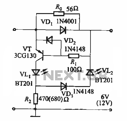
During the charging process, the green light-emitting diode (LED) VLi indicates that the battery is sufficiently charged, while the red light-emitting diode (LED) VLz illuminates when the battery is low. The circuit involves two light-emitting diodes (LEDs) serving as indicators...
This is a beta release schematic. Use at your own risk. The idea is to add this circuitry to a board that already has RAM at address 2000 and an 82C55 I/O chip to provide ports A, B, and...
The 555 timer IC is connected for Astable Operation, the clock pulses are fed to the 4017 IC via the 10K resistor. The 4017 is a 10 stage counter, therefore the sequence of the traffic lights is spread over...
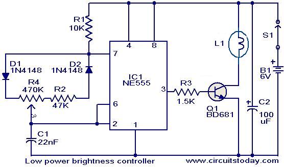
The circuit presented here is designed to control the brightness of low-power incandescent lamps. It utilizes the NE555 integrated circuit, configured as an astable multivibrator with a variable duty cycle. The output from the IC is connected to the...
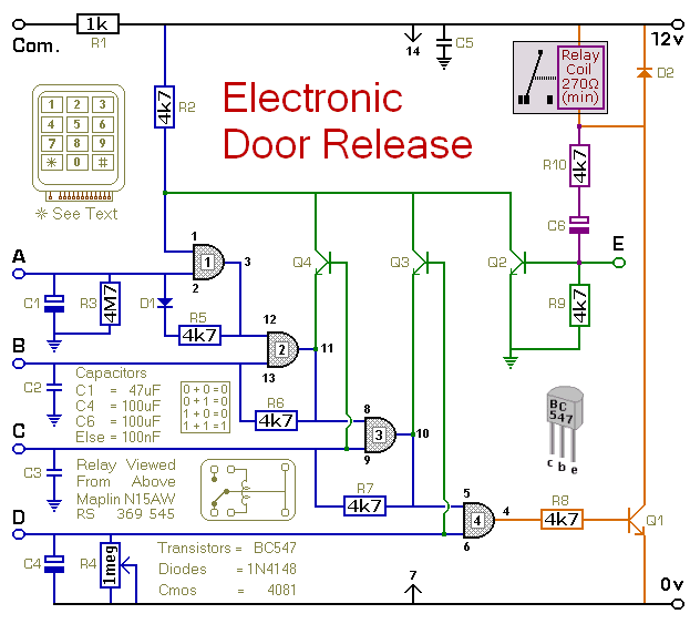
This circuit is designed to operate an electrical door-release mechanism, but it can also be utilized for other applications. When the user enters a four-digit code of their choice, the relay will energize for a preset time period. The...