
Play Games with Nixie Tubes

Preparation of the Commutators involves cutting a piece of 2" x 4 1/2" copper laminate board in half using a fine-toothed hacksaw blade. A cardboard wedge, with an angle of exactly 36 degrees, is created using a protractor. This wedge acts as a template to divide the laminate into ten equal segments of 36 degrees each, with light scoring on the copper to mark the divisions. Strips of 1/32" resist tape are placed over the score lines, ensuring the adhesive is firmly pressed onto the copper. Liquid resist is then applied over the entire board, leaving approximately 1/2" of copper exposed along the bottom. This process is repeated for a second copper plate, which is set aside to dry for about thirty minutes. Following this drying period, the resist tape is removed, and the plates are immersed in an etchant bath until all copper is removed from the grooves between segments and the strip along the bottom. Upon completion of the etching process, the boards are rinsed in clear running water, and a small amount of paint remover is brushed onto the surfaces to finalize the preparation.Nixie tubes were used for numeric - and sometimes alpha - displays back in the days before LEDs and LCDs. They were more light bulbs than tubes, but were encapsulated in evacuated glass shells like vacuum tubes and had round, multi-pin bases like tubes.
Separate filaments were provided for each character. There were two basic varieties: characters that displayed through the top of the tube, and characters that displayed through the side of the tube. Nixie tubes are popular with builders of retro equipment, and a lot of products are available for sale that incorporate them; e. g. , clocks, wrist watches, radios, clock radios, calendars, games, and much more. Electronic test equipment and medical instruments were big users of Nixie tubes. I remember a couple of the signal generators we used on the MPN-14 radar has Nixie tube displays. Supposedly the name "Nixie" derived from "NIX I", an abbreviation of "Numeric Indicator eXperimental No.
1, " as designated by the Burroughs Corporation sometime around 1955. The HB-106 Nixie tubes for this project can be purchased on eBay. You can throw away the whirling number wheels, the tumbling golf balls in the squirrel cage, and the gallopin` dominoes! It`s, much more fun to play Bingo, Roulette, Put-and-Take, Quizzo, boy-girl parlor games, and a host of other games - electronically!
By merely pressing a button, you can display a pair of randomly selected numbers for all kinds of numerical games in shining neon lights visible up to 20 feet away. This simple form of digital presentation is made possible by a modern little electron tube called a "Nixie.
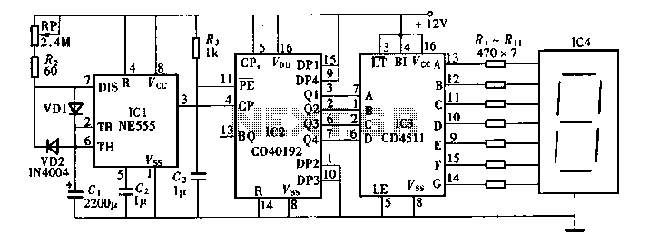
" Although specifically designed for computer panel read-out systems, the Nixie can be used in any device where any digit from 0 to 9 is to be displayed to a group of viewers. By using two Nixies, a pair of tiny electric motors, two printed-circuit commutator boards, and a suitable power source, you can make up a game machine that will put new life in the dullest party, spark community and church affairs, and even help the youngsters in the house practice their arithmetic; All you do is push the button.
Whirling motors flash the Nixie numbers inside the tubes too fast for the eye to follow. When the button is released, the motors come to rest, leaving two glowing numbers for everyone to see. Numerical selection is accomplished by a wiper installed on the motor gear. As the armature rotates, the wiper arm contacts successively ten copper segments separated by etched grooves on a printed-circuit board which serves as a commutator.
Prepare the Commutators. Using a fine-toothed hacksaw blade, cut a single piece of 2" x 4 1/2" XXXP copper laminate board exactly in half. Make up a little cardboard wedge having an angle of exactly 36 ° with the help of a protractor. Using the wedge as a template, divide the laminate into ten equal segments of 36 ° each, and score the copper lightly with a sharp-pointed tool to mark the divisions.
Lay strips of 1/32" resist tape over the score lines and press their adhesive sides firmly down on the copper. Carefully paint the liquid resist over the entire board, leaving about 1/2" of copper exposed along the bottom as shown in photo above.
Repeat this procedure with the second copper plate and set both pieces aside to dry for about a half hour. After this interval, remove the resist tape and immerse the plates in the etchant bath, leaving them in long enough to remove all the copper in the clear grooves between segments and the strip along the bottom.
When the etching is complete, rinse the boards in clear running water and then brush a little paint remover 🔗 External reference
Related Circuits
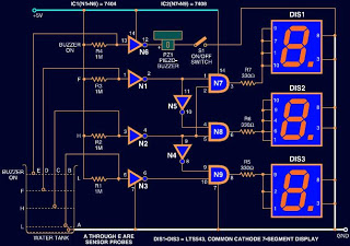
Circuits designed to indicate water levels typically consist of LEDs to represent the liquid level. However, this circuit utilizes a 7-segment LED display instead of standard LEDs for a numeric representation of the water level. Additionally, a buzzer is...
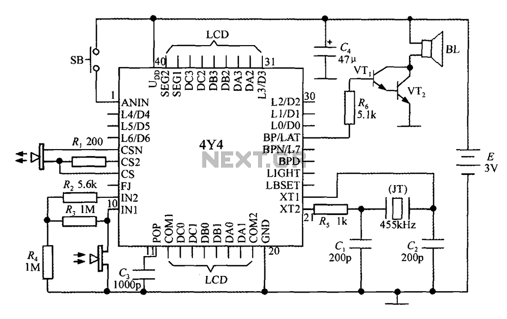
The 4Y4 is a monolithic liquid crystal display rangefinder circuit. The instrument comprises an ultrasonic transmitter, a receiver, an LCD display, buttons, switches, and a buzzer (or speaker). To simplify wiring, the 4Y4 is directly welded to the back...
The lab project involves a BCD counter and a 7-segment display using the CD4510BMS presettable BCD Up/Down Counter. The objective is to count from 32 to 84, rather than the default range of 00 to 99. The current setup...
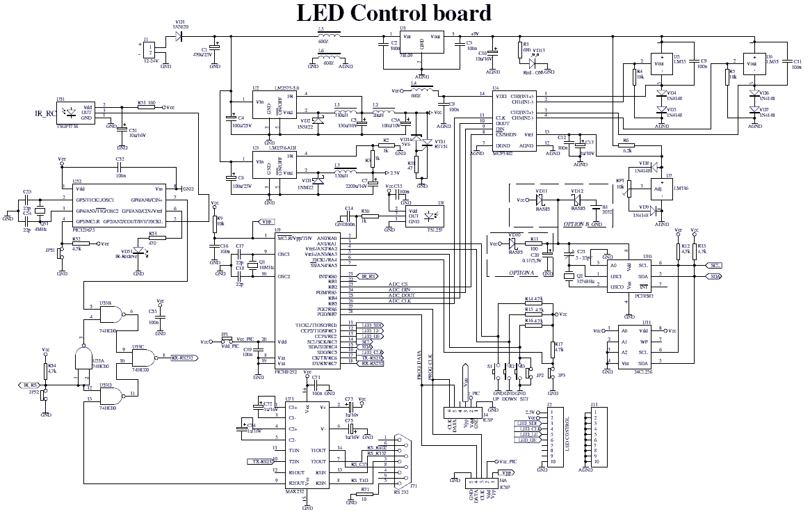
The device comprises two parts: LED control board and LED display board. The two PCBs are designed to fit together one behind the other using two sets of dual row connectors and 4 spacers. One of these connectors is...
This project introduces a fundamental electronics building block: the counter. By building a simple circuit that increments the display count every second, the operation of displays and their control will be learned. For those already familiar with driving displays...
Digital timers feature a clear and precise display. They represent time intervals based on pulse signals, which are decoded by a digital device with a digital display unit. The circuit described pertains to a digital display for these timers,...