
Water Level Indicator With 7-Segment Display PCB

This water level indication circuit employs a 7-segment LED display for clear numeric representation, enhancing visibility compared to traditional LED indicators. The inclusion of a buzzer provides an auditory alert for overflow conditions, ensuring that users are promptly notified to prevent potential water spillage. The circuit operates based on the principles of digital logic using the 7404 NOT gate IC, which is configured to respond to varying input voltages corresponding to the water level.
The 1M ohm resistor serves a dual purpose: it pulls the gate input high under normal conditions and establishes a reference voltage level for the operation of the circuit. As water fills the tank, the conductive properties of the water engage the low-level sensor, which is strategically placed to trigger the necessary logic changes in the circuit. The cascading logic levels from the NOT gates effectively convert the analog water level into a digital signal that can be interpreted by the display.
The display outputs "L" when the water level is low, transitioning to "H" for half-full and "F" for full, allowing for easy monitoring of the tank's status. This design can be integrated into automated water tank systems where it can control the motor operation based on the water level readings, thereby enhancing efficiency and convenience. The circuit's modular design allows for adaptability in various applications, making it suitable for both residential and industrial water management systems.Circuits available for indicating water level is usually consist of LEDs to indicate the liquid level. But this circuit uses a 7-segment LED display instead of normal LED`s for numeric display of water level.
Moreover, a buzzer is used to alert you of water overflowing from the tank. The circuit shows the water level by displaying L, H and F for lo w, half and full, respectively. You can use this circuit for water tank motor control or a stand alone circuit. pins of IC 7404 (NOT gate IC) are pulled high via a 1M ohm resistor. So it outputs a low voltage. As water starts filling the tank, a low voltage is available at the input pins of the gate and it outputs a high voltage. When the water in the tank rises to touch the low level sensor, pin 5 of gate N3 gets a low voltage and results in high output at pin 6.
Pin 6 of the gate is connected to pin 10 of gate N9, so pin 10 also goes high. Now as both pins 9 and 10 of gate N9 are high, its output pin 8 also goes high. As a result, positive supply is applied to DIS3 and it shows L` indicating low level of water in the tank. 🔗 External reference
Related Circuits
This circuit utilizes a relay to control a water pump, enabling automatic level control for a water reservoir or well. The shorter steel rod acts as the "water high" sensor, while the longer rod serves as the "water low"...
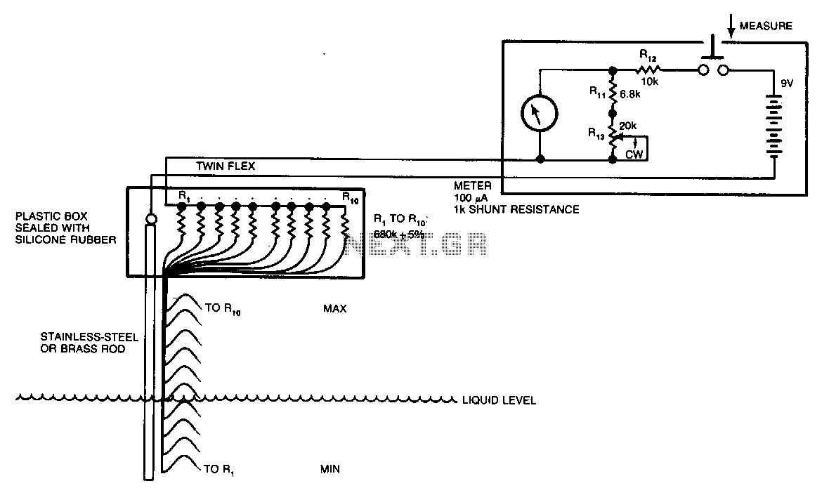
Although many circuits utilize the varying-capacitance method for measuring liquid levels, this straightforward resistive circuit is significantly easier to construct. Even a tank containing a liquid, such as water, has sufficient conductive salts in solution for this method to...
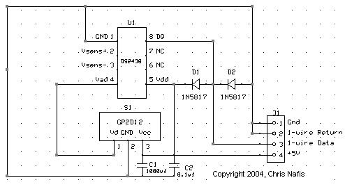
In home automation applications, there are instances where measuring the level of a body of water, such as in a pool or pond, is desired. The 1-Wire network facilitates easy interfacing of sensors to a PC or a simple...
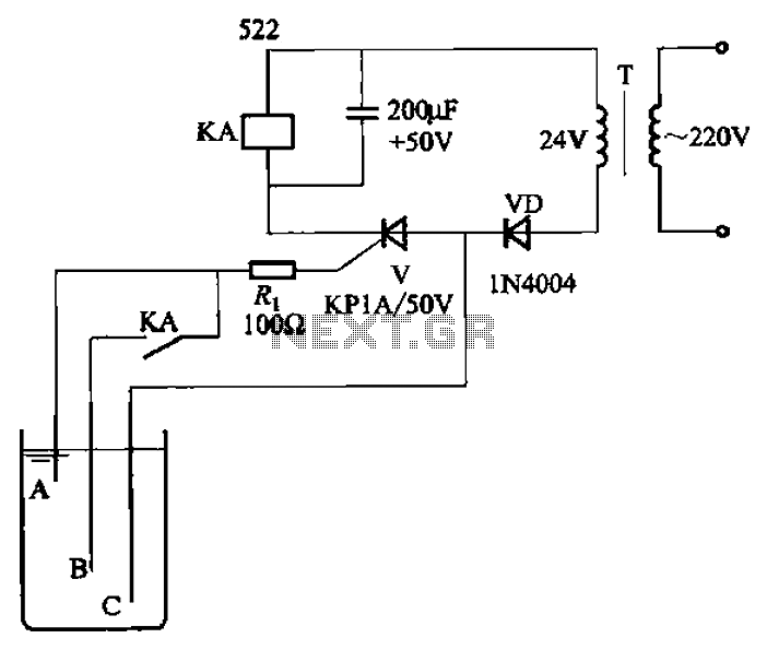
The circuit depicted in Figure 11-14 utilizes a unidirectional thyristor within liquid level automatic control systems. It incorporates electrodes that serve as sensing elements for detecting the level of water or other conductive liquids. The circuit features a current...
Application note on designing linear and switch-mode (switching DC-DC converter current source) battery charger applications that require external microcontrollers and related system-level issues for notebook computers. The application note provides guidance on the design of both linear and switching DC-DC...
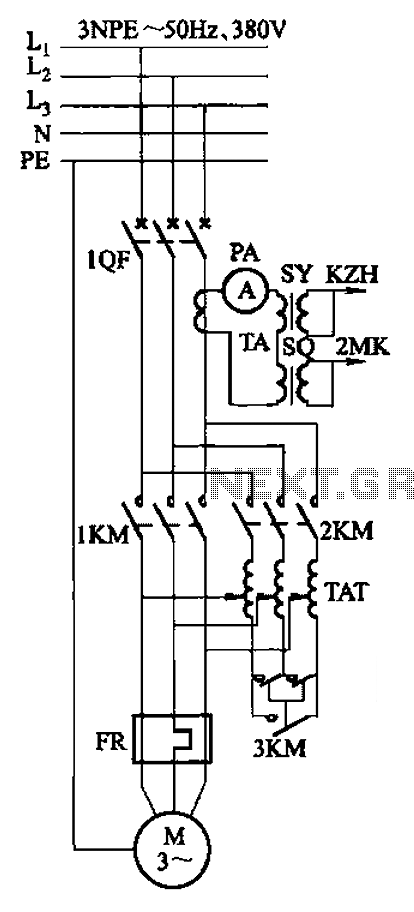
Autotransformer voltage starting, with an adjustable starting time of 30-60 seconds. It includes the SDJ electrode liquid level sensor of HJ-13 type, a pump control system box of HKD-21B type, 1MK level modules adopted by HKG-1SG type, 2MK start...