
Playing piano with optical sensors

To improve the responsiveness of an electronic keyboard, a systematic approach can be adopted that involves both hardware and software modifications. The keyboard's sensitivity can be influenced by several factors, including the type of switches used, the debounce time in the circuitry, and the software algorithms that interpret keystrokes.
1. **Switch Selection**: The choice of switches is critical. Mechanical switches, for example, often provide better tactile feedback and faster actuation times compared to membrane switches. The actuation point of the switch should be measured, as lower actuation points can lead to quicker responses.
2. **Debounce Circuitry**: In electronic keyboards, debounce time is the period during which the keyboard ignores additional inputs after a key is pressed to prevent multiple signals from being sent. Measuring the current debounce time and optimizing it can significantly improve responsiveness. This can be achieved through the use of hardware debouncing techniques, such as RC (resistor-capacitor) filters, or through software methods that implement algorithms to filter out noise from the key press signals.
3. **Microcontroller and Firmware**: The microcontroller used in the keyboard should be capable of processing input signals at high speeds. The firmware running on the microcontroller should be optimized to handle keystroke detection efficiently. This includes minimizing the latency in reading key states and processing them to send data to the host device.
4. **Signal Path Optimization**: Ensuring that the signal path from the switch to the microcontroller is as short and direct as possible can reduce delays. This may involve re-evaluating the PCB layout to minimize trace lengths and using high-quality components that do not introduce significant delays.
5. **Testing and Measurement**: The measurement of the fastest keystroke should include both the physical actuation time and the time taken for the signal to be processed and sent to the host. This can be done using high-speed oscilloscopes or specialized testing equipment that can capture the timing of the keystrokes accurately.
By addressing these factors, the overall responsiveness of the electronic keyboard can be significantly improved, resulting in a more satisfying user experience.trying to improve the responsiveness of an electric keyboard. He was unsatisfied with the lack of adequate sensitivity to keystroke. The first step in his process was to measure how fast the quickest keystroke actually is.. 🔗 External reference
Related Circuits
This application note describes the creation of a heart rate monitor utilizing an infrared (IR) LED and a phototransistor pair, with the waveform observed at the output of the phototransistor. The purpose of this project is to demonstrate a...
A Theremin typically operates by detecting hand proximity through the capacitive coupling method. The Theremin circuit illustrated in the schematic diagram below employs a different technique to control pitch. In this optical Theremin, the oscillator of the tone generator...
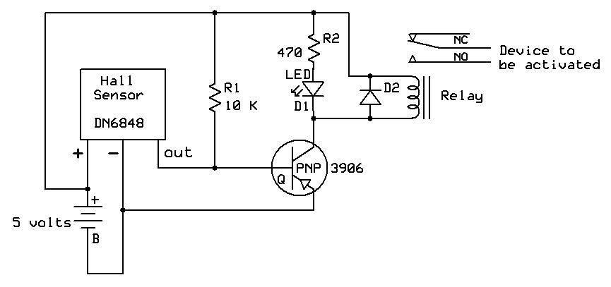
A sensor used in garden railway applications, Hall Effect sensors are the electronic equivalent of a reed switch. They can be thought of as a combination of a reed switch and a transistor. These sensors are commonly employed to...
The circuit provides three channels of optically isolated input suitable for various precision signal-acquisition applications. It operates using a single 15-V power rail with a ground common to the analog-to-digital converter. The multiplexer functions through a standard quad-channel optoisolator...
The Arduino microcontroller board can supply a current of 40mA from its output connections, with digital outputs fixed at 5V for "ON" and 0V for "OFF." This current is suitable for LEDs, but devices like motors, solenoids, and high-brightness...
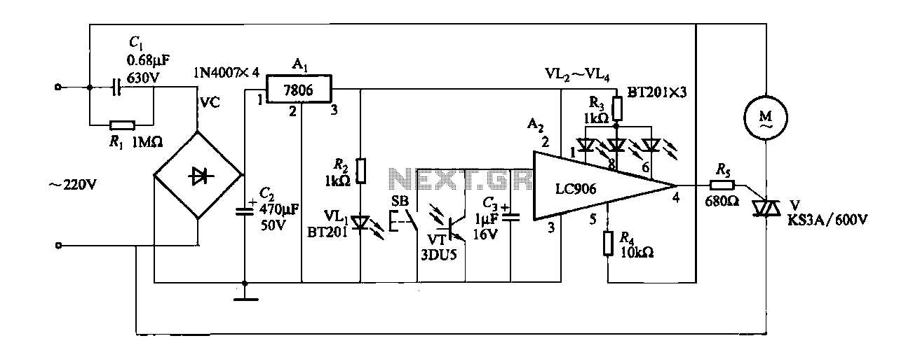
The ceiling fan speed control circuit depicted in Figure 3-6 utilizes a capacitor step-down method and a three-terminal fixed 7806 voltage regulator. It achieves fan speed control through the integrated circuit A2, which regulates the conduction angle of the...