
Please help with ultrasonic animal repeller circuit

The animal repeller circuit typically employs ultrasonic sound waves to deter animals from specific areas. The schematic generally includes a few key components: a power supply, an oscillator, a modulator, and a transducer.
1. **Power Supply**: This circuit is usually powered by a battery or a DC power source. The voltage requirements should be specified based on the components used, typically ranging from 5V to 12V.
2. **Oscillator**: The oscillator generates a high-frequency signal, which is often in the ultrasonic range (above 20 kHz). Commonly utilized components for this purpose include a 555 timer IC configured in astable mode or a microcontroller that can produce PWM signals. The frequency should be adjustable to cover different animal sensitivities.
3. **Modulator**: This section may include a transistor that amplifies the signal from the oscillator. The modulation can be achieved using a simple transistor switch that turns on and off at a specific frequency, creating a pulsing effect that can be more effective at repelling animals.
4. **Transducer**: The transducer converts the electrical signals into ultrasonic sound waves. Piezoelectric speakers are commonly used due to their efficiency in generating high-frequency sounds. The placement of the transducer is crucial; it should be positioned to maximize the coverage area.
5. **Additional Components**: The circuit may also include resistors, capacitors, and diodes for signal conditioning and protection. A potentiometer can be integrated to allow for frequency adjustment, enabling fine-tuning of the ultrasonic signal based on the specific environment or target animals.
For troubleshooting, one should verify the connections, check the power supply voltage, and ensure that all components are functioning correctly. Testing the output frequency with an oscilloscope can help determine if the oscillator is operating within the desired range. Additionally, ensuring that the transducer is operational and correctly positioned can significantly affect the circuit's effectiveness.HI FRIENDS, I HAVE A ANIMAL REPELLER CIRCUIT CIRCUIT DIAGRAM AS SHOWN: I HAVE WRKED ON THIS BUT NOT WORKING AS PREFERRED CAN U PLEASE CHECK THIS ONE.. 🔗 External reference
Related Circuits
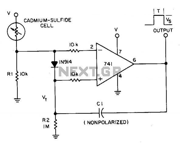
A photocell circuit provides automatic threshold adjustment. Monostable action prevents undesired retriggering of the output. With only one op amp IC, the circuit offers automatic adjustment of its trigger level to accommodate various light sources, changes in ambient light,...
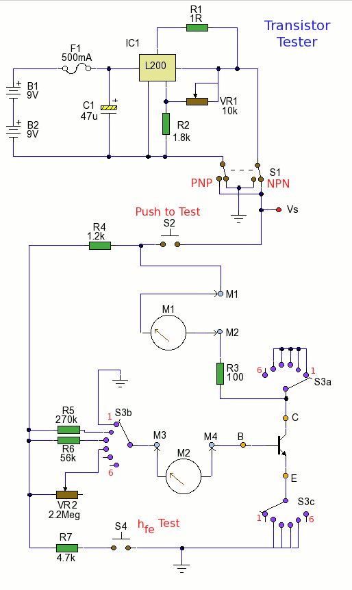
Using the tester is straightforward. Begin with the power off and insert a transistor into the test socket. Set switch S1 for either NPN or PNP configuration and rotate switch S3 to the desired test position. Adjust variable resistor...
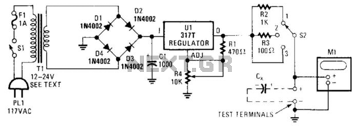
Sometimes electrolytic capacitors that are stored for a period may exhibit high leakage currents. Before utilizing these capacitors, it may be necessary to reform them. This power supply can be employed for the reforming process. Adjust resistor R4 according...
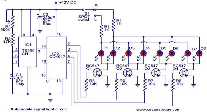
This is a simple circuit that can be used as a sequential signal light in automobiles. The circuit is based on two integrated circuits (ICs): a TS 555 CN CMOS timer IC and a CD4017 decade counter IC. The...
The working principle involves two pairs of photoelectric detection devices installed in the access channel. One side features light source A (transmitter) and photoresistor LDR1 (receiver) at the entrance of the channel, while the other side contains light source...
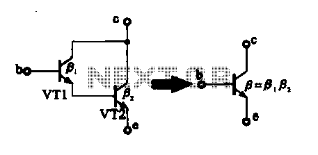
There are two composite pipe configurations: one consists of two transistors of the same type, while the other is made up of two different types of pipe configurations. The first configuration, utilizing two transistors of the same type, typically involves...