
PLL 41MHz reciever with 68HC711D3


The RX19 receiver implements a sophisticated frequency selection and signal processing system that enhances reliability and control in radio communication for remote-controlled devices. The system utilizes a locking phase loop to allow flexible frequency selection within the designated bands of 41 MHz and 72 MHz, accommodating a total of 142 distinct channels with a 5 kHz channel spacing.
Upon power-up, the RX19 defaults to the Normal Frequency (Fn) while also monitoring the Safety Frequency (Fs). The receiver is designed to prioritize the clearest signal from either frequency, ensuring optimal communication. The implementation of PPCM (Pulse Position Coded Modulation) allows for the integration of a PCM signature, which is crucial for identifying the transmitter. This coding method is designed to be compatible with existing receivers, allowing operators to switch between RX19 and RX17 without the need for modifications.
The RX19 employs a robust error-checking mechanism. Incoming signals are digitized and stored in a memory buffer for analysis before being sent to the servos. This process ensures that only valid signals, verified by specific criteria such as channel count and signal integrity, are relayed to the servos. If a signal fails to meet these criteria, the receiver retains the last valid data, thereby preventing erratic servo movements that could lead to loss of control or crashes.
In the event of signal anomalies persisting for more than 35 consecutive sequences, the RX19 automatically switches to the Safety Frequency (Fs) in search of a more stable signal. This automatic frequency switching is a critical feature that enhances the safety and reliability of the system, particularly in environments with potential interference.
Overall, the RX19 receiver exemplifies advanced technology in remote control systems, ensuring a high level of performance and safety through its innovative frequency management and signal processing capabilities.The quartz QZ1 of the preceding receivers which set the work frequency is not on the market any more. It is replaced by a locking phase loop allowing the free choice of an unspecified frequency on the band used, either the 41, or the 72 MHz.
The step between channels is 5 kHz, giving us 101 frequencies in 72 MHz and 41 in 41 MHz. In practice, the RX19 " scans " on the 2 frequencies chosen by the user. The first is called a Normal Frequency (Fn) and he other, a Safety Frequency (Fs). In fact, one does not take precedence over the other, except that when turning the power on, the RX19 starts by using Fn. In addition, it will use whichever signal of either Fn or Fs it will receive clearly. To be considered as " correct ", the received signal must have a " PCM signature ", identifying the transmitter’s owner. This code is a number selected between 0 and 255, inserted in the sequence. It should be noted that we do not use PCM (Pulse Coded Modulation) for the servo’s sequence. In our humble opinion, it only brings useless and even harmful complications, the signal to be transmitted being much more complex.
We remain faithful to the PPM (Pulse Position Modulation), a simple and effective method which allows easy insertion of our code. We call this new R/C technique, " PPCM " modulation. The figure above shows the principle used. The great advantage of PPCM is to remain completely compatible with existing receivers, the decoders being sensitive only to the front signal wave, they do not take any account of the position of the rear signal wave and are therefore completely unaware of the inserted code.
One can thus, with the same transmitter, control a RX19 (with PPCM) or a RX17 (without PPCM)! In a normal receiver, such as a RX17 or a RX18, the decoded signal arrives directly at the servos. If the signal is good, all is perfect. If it is bad, so be it and the servos go anywhere and the plane does aerobatics! Let us note how in one such receiver, a fault detector highlights an anomaly only after it has occurred. Obviously! In this case, the servos reacted... and made an inopportune movement... and the plane crashes! In the RX19, a received sequence is not exploited directly. See below . It is digitized, put in memory, then analyzed. If the result of the test is good: correct number of channels, duration of the time of synchro in the range exact PPCM signature...
then the new data replace the old ones in the memory buffer to the servos. If the test is bad, these data are not transmitted to the servos which continue to use the last received valid data. The result is that the servos do not make any erratic movement and the plane does not move. Any erroneous sequence is thus " erased ". The pilot does not feel anything if that occurs infrequently (there are 50 sequences a second!). However, if the anomaly lasts more than 35 consecutive sequences, that is to say approximately 0.7 second, the RX19 changes frequency considering Fn glitched and hoping to find on Fs, the other frequency, a better carrying signal.
If it is the case it remains on this second frequency. If the transmitter is with MANUAL change of frequency ( i.e. in the HF8 or HF9 modules of SUPERTEF) it is up to the pilot to note the loss of connection on the emitted frequency and to change it with the Fn/Fs switch. If this transmitter has an HF10 module which emits simultaneously on the two frequencies Fn and Fs, the pilot does not do anything and does not realize anything!
The choice of the useful frequency, at any given moment, is left to the RX19 to better judge on the matter! 🔗 External reference
Related Circuits
This frequency of this transmitter is PLL controlled which makes it very stable. The frequency is programmed in digitally way and can be changed very easy. Frequency range is about 50 to 150 MHz and the output power 100mW....
The operation of the circuit is managed by a microcontroller from MICROCHIP, specifically the PIC16F84. This microcontroller supports buttons and a 2-line, 16-character LCD display, along with the PLL circuit SAA1057. The voltage-controlled oscillator (VCO) is implemented using transistor...

The main oscillator is printed in blue and is voltage controlled. In this construction, the VCO range is 88 to 108 MHz. As you can see from the blue arrows, some energy goes to an amplifier and some energy...
This small FM transmitter includes a limiter, a microphone amplifier, and a PLL digital tuning. All the parts are placed on one circuit board. The RF power is switchable between 1 W (HI) and 0.2 W (LO). Technical specifications:...
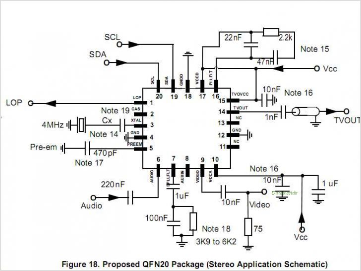
MC44BS374CA: PLL Tuned UHF and VHF Audio Video High Integration Modulator MC44BS374CA The MC44BS374CA Audio and Video Modulator is for use in VCRs, set-top boxes, and similar devices. By Freescale Semiconductor, Inc The MC44BS374CA is a highly integrated audio and...
This receptor is born of our annoyance against the irritating problem of Quartz: With the RX21, completed research of cut crystal for your personal rating, you have with him, access to ALL band frequencies, in steps of 5 kHz!...