
Frequency Multiplier Without Pll Circuit

This is achieved by omitting the most significant bits of counter B. Since the number loaded into counter B is 2M times smaller than that in the latch, the frequency of the carry impulses from counter B is twice that of the impulses at the output of the differentiator. These carry impulses are fed into a D flip-flop, which divides their frequency by two. As a result, the output frequency is twice the input frequency fL, provided that the frequency of the impulse generator is significantly greater than 2Mf.
The described circuit utilizes a differentiator to convert a rectangular input signal into short pulses, which are critical for counting operations. Counter A, which operates at a much higher frequency than the input signal, captures the number of these short pulses. The latch serves as a temporary storage element, ensuring that the count is preserved momentarily before being transferred to counter B. The division of the count by 2M is accomplished through the design of counter B, which discards the most significant bits, effectively scaling down the input count.
The interaction between the counters and the latch is essential for maintaining an accurate representation of the pulse count relative to the input signal. The D flip-flop's role in frequency division further enables the system to produce an output frequency that is twice that of the input frequency, enhancing the overall functionality of the circuit. This design is particularly useful in applications where precise frequency scaling and counting of high-speed signals are required. An input rectangular signal is differentiated and short impulses are formed from its edges. These impulses write the content of counter A to a latch that clears the counter after a very short time. Counter A counts impulses of the frequency fo that are much greater than that of the input signal. The pulses come from an impulse generator. Thus, the number, which is written to the latch, expresses the number of these impulses between the edges of the input signal.
The impulses from the same generator pass to (reverse) counter B. The carry impulse loads the content of the latch to counter B. The latch is connected with the reverse counter such that the number written to this counter is 2M times smaller than the number introduced to the latch. This can be readily achieved by omitting most significant bites -f counter B. Because the number loaded to counter is 2M times smaller than the number in the latch, the carry impulses of counter have frequency 2 times greater than the frequency of the impulses at the output of the differentiator. The carry impulses are fed to a D flip-flop, which divides their frequency by two. In this way, the output frequency is 2 greater than input frequency fL as long as the frequency of impulse generator/ is much greater than 2Mf.
Related Circuits
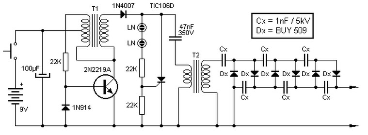
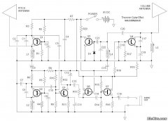
This high voltage source consists of an inverter built around a transistor that generates pulses of 150V. These pulses are supplied to an inverter made of a thyristor and a capacitor, which is connected in series with transformer T2....
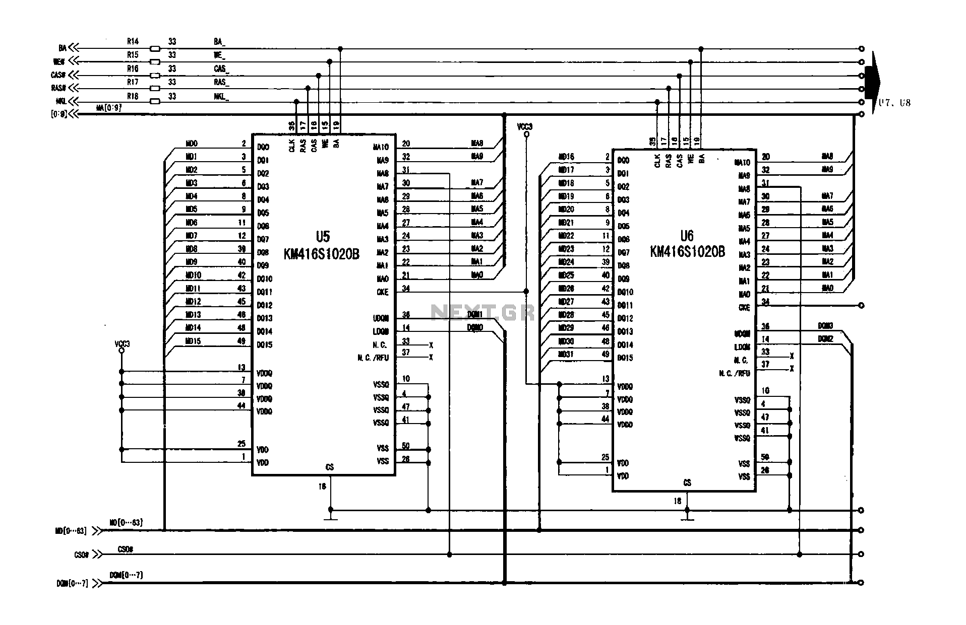
A digital signal processing circuit that operates in conjunction with a memory system for temporarily storing image data. The DPTVT-3D/MV digital processing chip requires four KM416S102 memory units, each providing 16 MB of digital memory. The circuit structure is...
This microphone preamplifier utilizes the low-noise integrated circuit (IC) uA739. It serves as a practical example of designing an effective preamplifier for dynamic microphones. The IC contains two identical integrated preamplifier circuits, with the second preamp functioning in the...
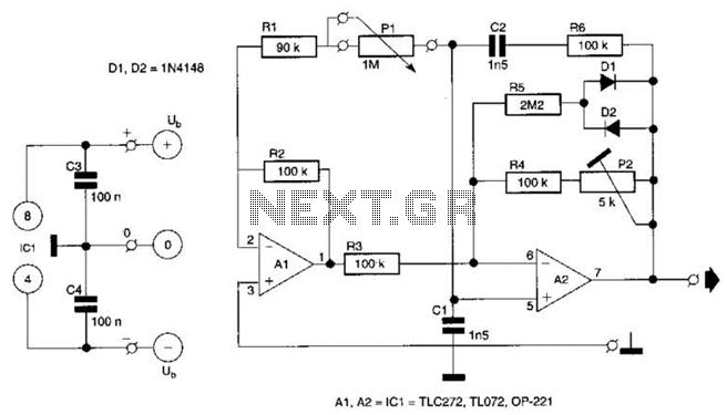
This circuit utilizes a single potentiometer to control a frequency range from 300 Hz to 3000 Hz. A FET operational amplifier is employed at stages A1 and A2. The upper frequency limit is dictated by the gain-bandwidth product of...
The PT2399 digital echo circuit schematic is an electronic design that utilizes the PT2399 integrated circuit (IC) for audio applications. This digital echo processor, based on CMOS technology, incorporates both analog-to-digital conversion (ADC) and digital-to-analog conversion (DAC) processes for...
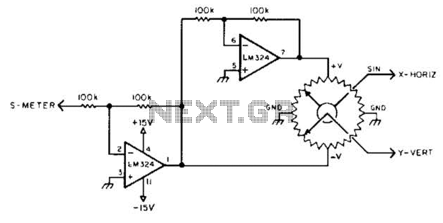
To display polar quantities, which include both the magnitude and direction of a received radio signal, a sine and cosine voltage proportional to an angle corresponding to the antenna direction is required. This setup utilizes a sine-cosine potentiometer connected...