
Pocket-sized geiger counter

The described circuit operates on a 6.75 V mercury battery, which is a compact power source suitable for low-power applications. The counter is designed to measure pulse rates, with the output displayed on a 1 mA analog meter and an associated audible signal. The use of a regulated 900 V supply is critical for maintaining the performance of the counter tube, ensuring consistent operation and accuracy in pulse detection.
The multivibrator circuit, constructed using a differential power amplifier (IC2), is responsible for generating the necessary high-voltage pulses to drive a step-up transformer. This transformer increases the voltage to the required 900 V for the counter tube. The comparator circuit (IC1) plays a vital role in controlling the duty cycle of the multivibrator, which in turn stabilizes the output voltage, ensuring that the counter tube operates efficiently without fluctuations that could affect measurement accuracy.
The regulated supply is designed to be energy-efficient, drawing less than 2 mA, which is particularly advantageous for battery-operated devices, extending their operational lifespan. The one-shot multivibrator (IC3) produces output pulses of fixed width and amplitude, which are essential for providing a reliable pulse rate to the meter. The average current through the meter correlates directly with the pulse rate output from the counter tube, facilitating straightforward interpretation of the measurements.
At full-scale deflection, the meter reads 1 mA, which corresponds to a pulse rate of 5000 counts per minute or approximately 83.3 pulses per second. For ease of use and calibration, a specific checkpoint is marked on the meter scale to indicate a pulse rate of 3600 parts per million (ppm), equating to 60 pulses per second. This feature enhances the usability of the device by allowing users to quickly reference standard measurement rates during operation.A single 6.75 V mercury battery powers the counter, which features a 1 mA count-rate meter as well as an aural output. A regulated 900 V supply provides stable operation of the counter tube. A multivibrator, built around a differential power amplifier IC2, drives the step-up transformer. Comparator IC1 varies the multivibrator duty cycle to provide a constant 900 V. The entire regulated supply draws less than 2 mA. A one-shot multivibrator, built with IC3, provides output pulses that have constant width and amplitude.
Thus the average current through the meter is directly proportional to the pulse-rate output from the counter tube. And the constant-width pulses also drive the speaker. Full-scale meter deflection (1 mA) represents 5000 counts/min, or 83.3 pulses/s. A convenient calibration checkpoint can be provided on the meter scale for 3600 ppm (60 pulses/s.)
Related Circuits

A simple frequency meter or frequency counter circuit featuring an LCD display and an AVR microcontroller. This includes a DIY schematic circuit diagram and embedded C code. The frequency meter circuit is designed to measure the frequency of input signals...
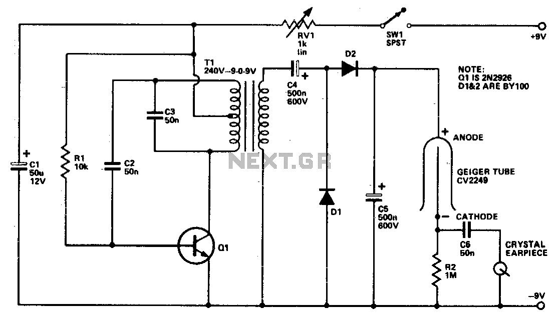
The Geiger tube requires a high voltage supply, which is formed by Q1 and its associated components. The transformer is connected in reverse; the secondary is configured as a Hartley oscillator, while R1 provides base bias. Diodes D1 and...
This circuit measures the distance covered during a walk. The hardware is housed in a compact box that can be conveniently placed in a pants pocket. The display is designed as follows: the leftmost display, D2 (the most significant...
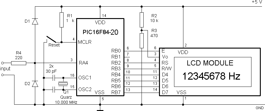
It consists only from Microchip PIC 16F84 cpu and LCD text module. Author states that this counter is capable metering frequencies from 400Hz to 50MHz. I used faster, 20MHz version of 16F84A-20I/P, and it managed to count 80MHz oscillator...
For convenient reading, the display of this tachometer circuit shows the reading in hertz directly. The conversion time will be equal to the gating time. The tachometer circuit is designed to provide a direct digital readout of rotational speed in...
Battery eliminators are circuits that create a DC power supply from AC mains. Essentially, battery eliminator circuits consist of a step-down transformer, rectifier, and voltage regulator. A simple circuit of a multipurpose battery eliminator features various output voltage ranges...