
PoE+ Circuit Delivers 13W to 70W for Powered Devices (PDs)
")
Power over Ethernet (PoE) technology enables the delivery of electrical power along with data over standard Ethernet cables, allowing devices such as IP cameras, VoIP phones, and wireless access points to receive power without the need for separate power supplies. The PoE Plus standard, defined by IEEE 802.3at, extends the capabilities of the original PoE standard (IEEE 802.3af) by allowing for a maximum power output of 30 W per port.
To implement a PoE Plus system capable of delivering this power level, an external MOSFET is integrated into the circuit design. The MOSFET serves as a switch that regulates the flow of power to the powered device (PD). The controller, designed for compatibility with the older PoE standard, manages the detection and classification of the powered device, ensuring that the appropriate power level is supplied.
The circuit typically includes a power sourcing equipment (PSE) component that interfaces with the Ethernet cable, supplying power through the spare pairs or the data pairs, depending on the wiring configuration. The external MOSFET is controlled by the PSE, which adjusts the gate voltage to modulate the power delivered to the PD based on its requirements.
In summary, the combination of an external MOSFET and a compatible controller allows the implementation of a PoE Plus system that meets the 30 W power requirement, enabling efficient power delivery for a variety of networked devices while adhering to the established standards.It is possible to implement a PoE Plus-required power level of 30 W, with the aid of an external MOSFET and a controller designed for the older standard.. 🔗 External reference
Related Circuits
A continuously running cooling fan can be a significant nuisance and is not essential for most instruments. The 12V smart fan control presented here allows the fan to operate only when necessary. The 12V smart fan control circuit is designed...

This gated 1-kHz oscillator provides press-to-turn-off functionality, along with waveforms available at the output of pin 3 and across capacitor C1. The gated 1-kHz oscillator circuit is designed to generate a square wave output at a frequency of 1 kHz....
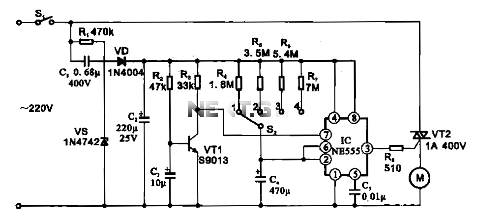
The fan motor driving circuit is depicted as a basic configuration comprising a power circuit and a motor drive circuit. The power supply circuit primarily consists of a power switch (SI), a capacitor (C1), resistors (R1), a Zener diode...
This signal generator is designed for the realignment of radio receivers. The unit is inexpensive and relatively simple but adequately serves its intended purpose. However, the output is not a pure sine wave, which may make it unsuitable for...

This dimming-controlled LED driver electronic circuit requires an input voltage of 36 volts and will provide an output voltage of 24 volts at a maximum current of 700 mA. The described dimming-controlled LED driver circuit is designed to efficiently convert...
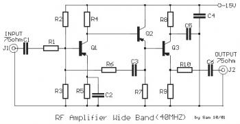
This is a 40 MHz RF amplifier circuit. The sensitivity of a receiver can be significantly enhanced by integrating this circuit between the receiver and the antenna. The amplifier does not utilize resonant circuits and is suitable for both...