
RF Signal Generator circuit

The signal generator described serves as an essential tool for aligning radio receivers, particularly in amateur radio applications. Its configuration as a Colpitts oscillator, utilizing a high-gain FET, allows for adjustable frequency output, which is critical for tuning various radio frequencies. The use of variable capacitors and switched inductors enables flexibility in frequency selection, although the limited availability of inductors may necessitate compromises in the range of frequencies that can be generated.
The integration of K-ID and K-ID2 chips enhances the functionality of the system, providing a robust solution for beacon and CW identifier applications. With a non-volatile memory capacity of 512 bytes, these chips allow users to store and transmit messages effectively, making them suitable for amateur radio and other communication applications.
The ADTRX1 transceiver represents a significant advancement in HF transceiver technology, merging analog and digital methods to create a versatile platform for both beginners and experienced users. The design emphasizes simplicity and accessibility, making it an ideal starting point for those interested in exploring software-defined radio techniques. As the industry shifts towards software-based specifications, the ADTRX1 exemplifies how traditional hardware concepts can be adapted to meet modern requirements.
The modifications planned for the fox hunting PIC assembly code illustrate the adaptability of the system to conform to evolving standards in amateur radio competitions. By allowing for timed transmissions, the system enhances the competitive experience while ensuring compliance with IARU regulations. This adaptability and the emphasis on user-friendly design highlight the ongoing evolution of amateur radio technology and its community-driven innovations.This signal generator is intended for realignment of radio receivers. The unit is cheap and fairly basic, but perfectly adequate for its intended purpose. However, the output is not a pure sine wave, so the unit may not be suited for more exacting electronic development work. TR1 is a high gain FET (Field Effect Transistor) and is configured as a Colpitts style oscillator. The oscillation frequency is set by the variable capacitor (C1+C2) and the five pairs of switched inductors. There is significant overlap between the ranges, due to the limited range of readily available inductors.
However even by using specially would inductors, four frequency bands would have been needed to cover the range. K-ID and K-ID2 This chip is designed expressly for dedicated beacon or CW identifier applications. It is very flexible and has the advantage of a very large message storage bank (512 bytes) which is non-volatile.
Keywords: homebrew, SDR, transceivers, homemade, hamradio, amateur radio, block diagram, circuits, schematic, receiver, digital, module, kit, project, low cost, PIC. HF SDR transceiver called ADTRX1 (analog + digital) is compilation of the results and previously published designs.
ADTRX1 is working to the 35 MHz and it is a very simple and promising design all with classic size thru holes components. It is very good introduction in to the new SDR technique of the HF transceiver design. Most of demanding specification for HF transceivers are in software now, not in hardware like in classic HF transceiver design.
Part 1 is giving description main ADTRX1 board, results and basic connections I am going to modify a radio-orienteering (fox hunting) PIC asm (written by yo5ooe ) code to fit the new IARU rules for the new type of fox hunting contest. The foxes are on a 5 minutes cycle. Fox 1 will transmit MOE in CW for one minute and then Fox 2 will transmit MOI for one minute and then Fox 3 will transmit MOS for one minute and then Fox 4 will transmit MOH for one minute and then Fox 5 will transmit MO5 ³ for one minute.
The foxes are on a 1 minutes cycle. Fox 1 will transmit MOE in CW for 12 seconds and then Fox 2 will transmit MOI for 12 seconds and then Fox 3 will transmit MOS for 12 seconds and then Fox 4 will transmit MOH for 12 seconds and then Fox 5 will transmit MO5 ³ for 12 seconds. 🔗 External reference
Related Circuits

R4 prevents the output voltage from drifting toward one of the supply rails of the operational amplifier. It is understood that R4 should have a high resistance, although the reason for this is unclear. The schematic appears to be...
This is a circuit which I originally included in my book, 22 Tested Transistor Projects, published by Babani Press in 1976 (ISBN 0 900162 63 S). It is one I had great fun with. It uses the PUT Complimentary...
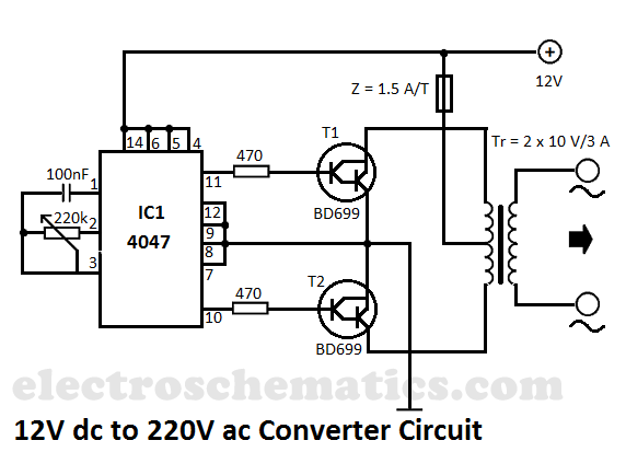
This DIY 12V to 220V voltage converter is built with the CMOS 4047, which serves as the main component of this compact voltage converter that transforms 12V DC into 220V AC. The 4047 is configured as an astable multivibrator,...
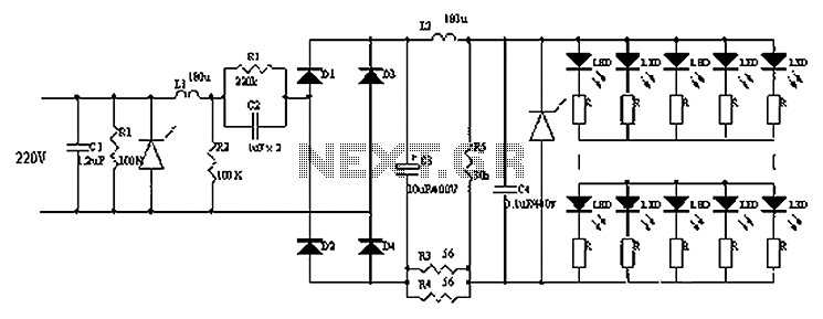
Circuits C1, R1, varistors, L1, and R2 form a filter circuit that includes a primary power supply capable of filtering out transient overvoltage inputs. The circuit also consists of C2 and R2, with additional components C3, C4, and L2....
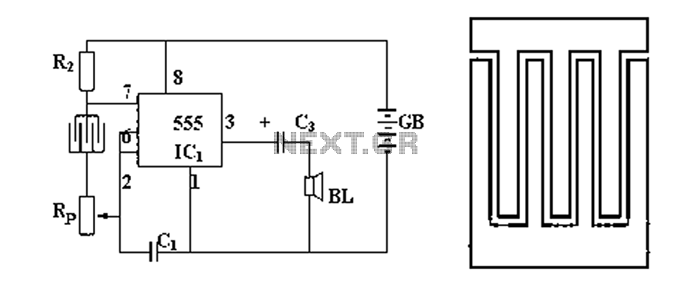
Figure 1 illustrates a circuit diagram related to an audio circuit that incorporates a resistance between two leads connected to a rain alarm probe. Figure 2 demonstrates the connection of a capacitor to the probe within the audio circuit....
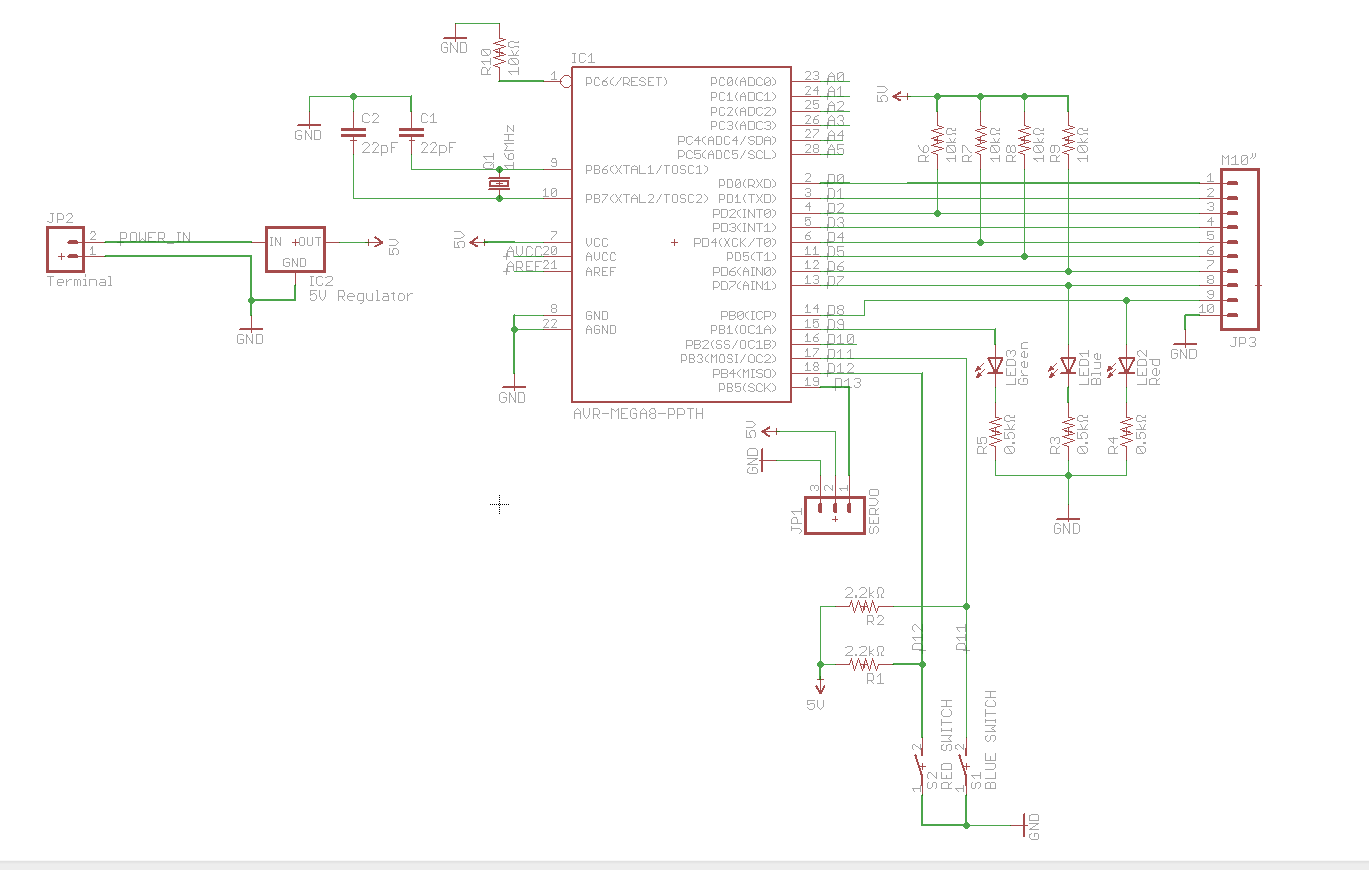
A circuit utilizes a keypad, a servo, and several LEDs, connected to an Arduino Uno. The objective was to integrate all components onto a single PCB, effectively creating a custom version of the Arduino. Upon startup, the red LED...