
40mhz rf amplifier circuit

The 40 MHz RF amplifier circuit is engineered to enhance the performance of radio communication systems by boosting the signal strength before it reaches the receiver. The circuit operates effectively across a frequency range of medium to short waves, making it versatile for various RF applications. With a gain of 20 dB, this amplifier significantly amplifies weak signals, thereby improving the overall sensitivity of the receiving system.
The power supply requirement of 12 to 15 V DC ensures that the amplifier operates efficiently while consuming a modest current of 7 mA. This low power consumption is beneficial for portable applications where battery life is a concern. The choice of a 75-ohm coaxial cable for both input and output connections is crucial, as it minimizes signal reflection and loss, ensuring optimal performance.
In terms of functionality, this RF power amplifier is designed to convert low-power RF signals into higher power outputs, which is essential for driving antennas in transmitter applications. The design emphasizes high efficiency and output power, which are critical for achieving effective transmission without excessive heat generation. The amplifier's characteristics, such as return loss and gain, are optimized to ensure that the signal integrity is maintained throughout the amplification process.
Overall, this 40 MHz RF amplifier circuit serves as a vital component in enhancing the performance of RF systems, particularly in applications where signal strength and clarity are paramount. Its design considerations and operational parameters make it suitable for a wide range of applications in the field of electronics and communication.This is the 40Mhz RF amplifier circuit. The sensitivity of a receiver may be significantly increased if this circuit is inserted between the receiver and the antenna. The amplifier circuit does not use resonant circuits and is suitable for both medium and for the short waves, up to 40 MHz.
The gain of this RF amplifier is 20db and it consumes 7mA electric current, when it is supplied with 12 until 15V dc. The input and the output should be connected with coaxial cable, resistance 75ohm. An RF power amplifier is a type of electronic amplifier which is utilised to convert a low-power radio-frequency signal into a larger signal of significant power, usually for driving the antenna of a transmitter. It is usually optimized to have high efficiency, high output Power (P1dB) compression, good gain, good return loss on the input and output, and optimum heat dissipation.
The basic applications of the RF power amplifier include driving to another high power source, driving a transmitting antenna, microwave heating, and exciting resonant cavity structures. Among these applications, driving transmitter antennas is most well known. 🔗 External reference
Related Circuits
The microphone has high sensitivity in the audio range, but in the ultrasonic range, the sensitivity decreases rapidly. The receiver is very sensitive. To prevent overdriving and feedback due to the high sensitivity of the microphone in the audio...
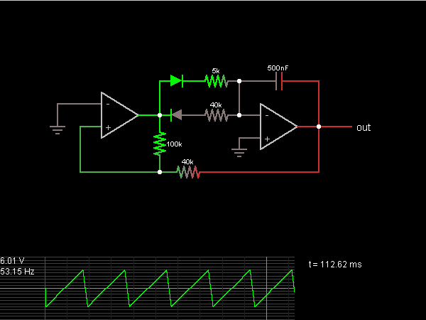
A step sequence can be applied that triggers every other step, allowing the activated steps to rise with each activation. This Low-Frequency Oscillator (LFO) can then be used to modulate other parameters of the plugin to enhance the sound....
The following diagram illustrates the circuit of a Stereo OTL Audio Amplifier. It is based on an integrated circuit (IC), making the circuit design straightforward. The amplifier project can utilize ICs such as LM379, LM377, or LM378. According to...
This is a transistor tester integrated into a circuit or printed circuit board (PCB). It is utilized when a project does not function correctly, allowing for the testing of electronic components. The transistor tester is a crucial tool in electronic...
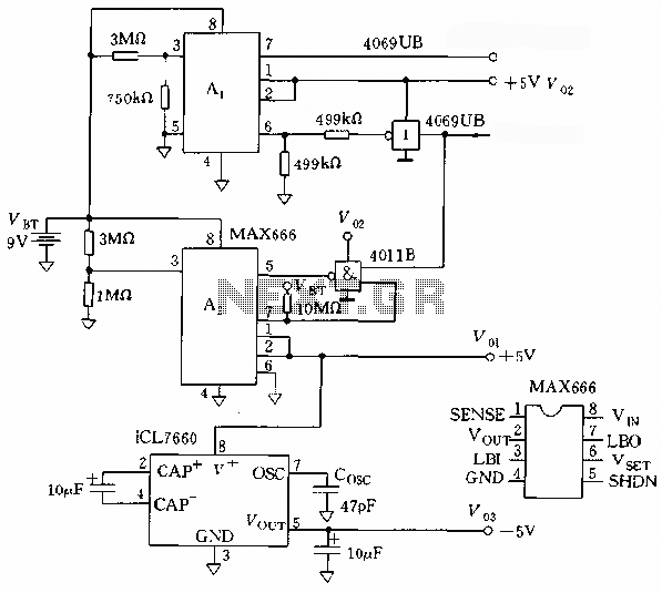
The microprocessor utilizes a linear regulator power circuit that is constructed using two MAX666 devices. The power supply for the CPU and A/D converter is connected to A2, while the RAM and real-time clock receive power from A1. The...
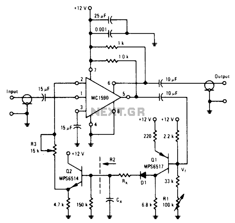
An amplifier designed to achieve a voltage gain of approximately 20, utilizing the MPS6517 PNP transistor in the emitter follower configuration. The RI controller allows for adjustment of the transistor's quiescent point. The output signal is activated only when...