
Police bicycle siren circuits
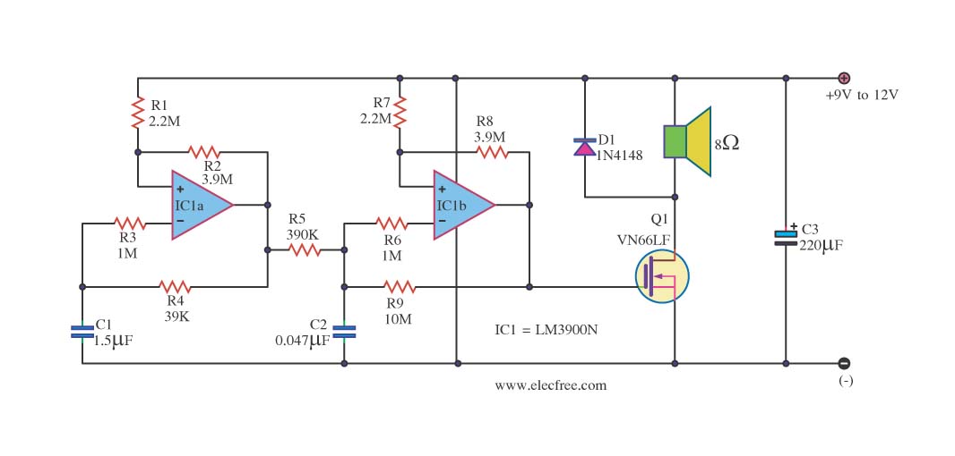
The sound generator circuit employs an op-amp configuration to produce a variable frequency output, which is essential for generating the siren effect. The operational amplifier IC1 is configured in a feedback loop with capacitors and resistors that determine the frequency and amplitude of the output signal. The diodes D1 and D2 serve to shape the waveform, ensuring that the output maintains a specific form conducive to alarm applications.
The charging and discharging of capacitor C3 is a critical aspect of this circuit. When switch S1 is pressed, C3 begins to charge, storing energy that is later released to create the sound pulse. The resistor R7 plays a vital role in controlling the current flow to the op-amp, preventing overload and ensuring stable operation of the circuit. The detector circuit formed by resistors R1 and R2 is responsible for monitoring the output signal levels and providing feedback to maintain the desired operational characteristics.
Transistor Q1 (BC639) acts as a power amplifier, allowing the circuit to drive the loudspeaker SP1 effectively. The biasing of Q1 is crucial, as it determines the transistor's operating state. When Q1 is biased into the active region, it allows for significant current flow through SP1, resulting in the loud siren sound that is characteristic of alarm systems.
Overall, this sound generator circuit is a robust solution for alarm applications, utilizing fundamental electronic components to create a reliable and effective warning signal. Its design ensures that it can be easily integrated into various alarm systems while providing clear and audible alerts.This circuit is the sound generator super siren, for use be alarm signal get by live frequency generator circuit that use, op-amp circuit. The principle works to are while still no press switch S1 will still have no the loud sound comes out from a loudspeaker SP1.
When do pressure switch S1 then liberate C3 do something charge full until while press switch S1 and discharge go out. When liberate switch S1 come in at R7. Which perform in something limit current come in at 3 Non inverting legs of IC1a. By IC1, D1, D2, C1, C2 and R5 build be sound generator signal circuit then export come to way pin 6 of IC1a come to reach at pin 3 (Noninverting) of IC1b. By have R1 and R2 build be Dectector circuit. For do fining level has signal then signal to come out the way pin 7 of IC1b which will have flowing through comes in at pin B of Q1 for do something bias give Q1(BC639) bias.
When Q1(BC639) work then make SP1 make a noise loud come out and make a noise poor loud C3 discharge be finished SP1 then stop make a noise loud. 🔗 External reference
Related Circuits

The sound produced imitates the rise and fall of an American police siren. When first switched on, the 10 µF capacitor is discharged, and both transistors are off. When the push button switch is pressed, the 10 µF capacitor...
Some good inverter circuits I found oscillate at approximately 50 to 60 Hz. They are likely capable of handling up to two amps; any more than that will cause them to automatically shut off. If there are questions, please...
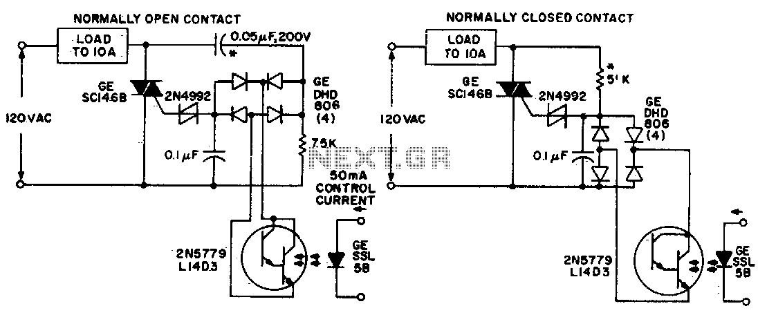
Both circuits utilize the GE SC146B, a 200 V, 10 A Triac for load current contacts. These triacs are activated by standard SBS (2N4992) trigger circuits, which are managed by a photo-Darlington configuration, functioning through the DA806 bridge as...
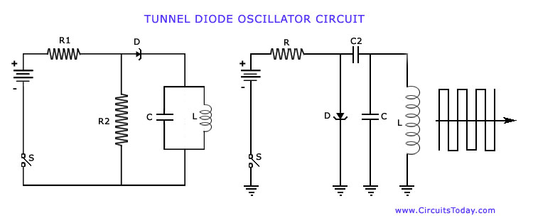
The operation of Negative Resistance Oscillators, including types such as Dynatron and Tunnel Diode Oscillator, along with their characteristics and circuit diagrams, is explained. Negative resistance oscillators are electronic circuits that exploit the phenomenon of negative resistance to generate oscillations....
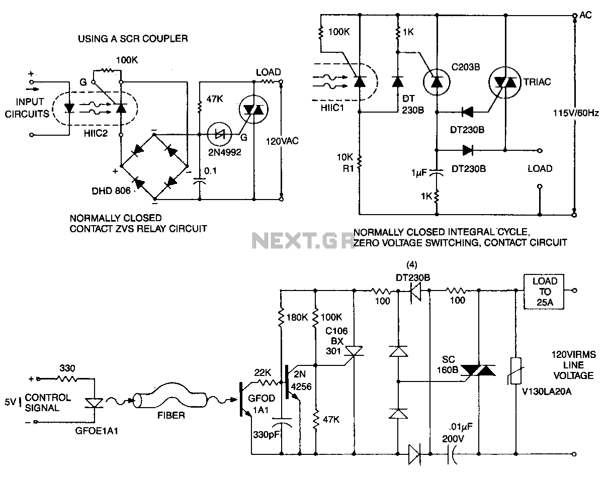
This circuit is effective for lamp and heater loads. Some circuits driving reactive loads require integral cycling and zero-voltage switching when an identical number of positive and negative half-cycles of voltage are applied to the load during a power...
This site addresses a range of subjects pertaining to circuits and electronics. Some of the topics discussed on this site include: * Alternating Relay Switch * Photoswitch Relay. The site serves as a comprehensive resource for understanding various electronic components...
Warning: include(partials/cookie-banner.php): Failed to open stream: Permission denied in /var/www/html/nextgr/view-circuit.php on line 713
Warning: include(): Failed opening 'partials/cookie-banner.php' for inclusion (include_path='.:/usr/share/php') in /var/www/html/nextgr/view-circuit.php on line 713