
inverter circuits

Inverter circuits are essential components in various applications, converting direct current (DC) into alternating current (AC). The typical frequency of operation for these circuits is between 50 Hz and 60 Hz, which aligns with standard power supply frequencies used in many regions worldwide. The inverter circuits discussed are designed to handle loads up to two amps, making them suitable for low to moderate power applications.
The design of these inverters typically involves a few critical components: a DC power source, oscillators, switching devices (such as transistors or MOSFETs), and a transformer. The oscillator generates a square wave signal at the desired frequency. This square wave is then used to turn the switching devices on and off, creating an alternating current output. The transformer steps up or steps down the voltage as needed while isolating the load from the DC source.
Protection mechanisms are often integrated into inverter designs to prevent overheating and overcurrent conditions. When the load exceeds the two-amp threshold, the inverter automatically shuts off to protect the circuit from damage. This feature is crucial for maintaining the reliability and longevity of the inverter.
Inverter circuits can be applied in various scenarios, including powering small household appliances, charging batteries, and providing emergency backup power. Understanding the specifications and limitations of these circuits allows for effective integration into electronic systems, ensuring optimal performance and safety.Some good inverter circuits I fond they, oscillate at about 50 to 60Hz. They will probably handle up to about two amps any more and the will auto shut off. Have questions ask me leave your questions in the comment box or email me at ericgoodchild@yahoo. com 🔗 External reference
Related Circuits
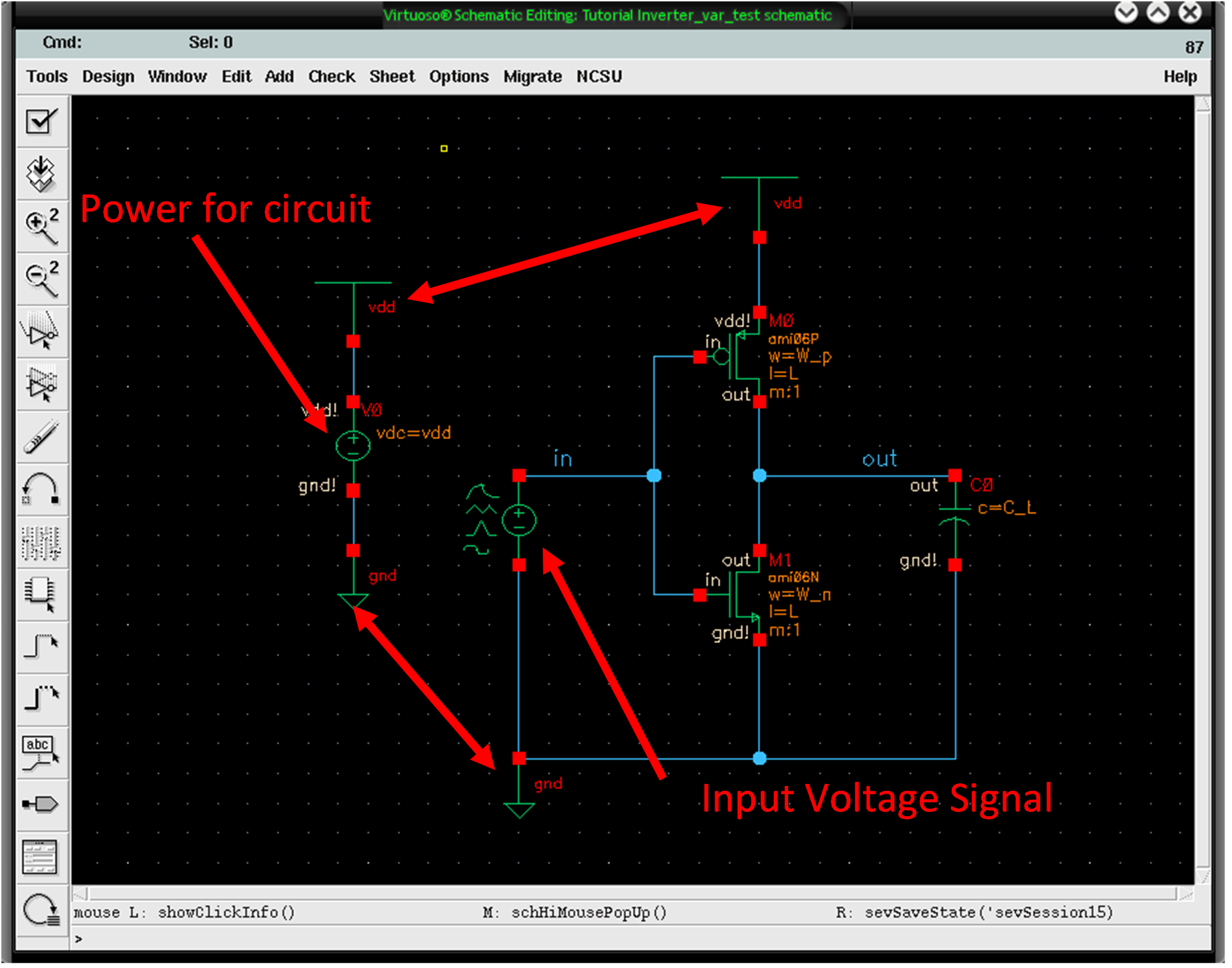
The differences in strengths between PMOS and NMOS transistors can be observed through a simple test by gradually increasing the input voltage and noting the point at which the output voltage changes from 5V to 0V. To conduct this...
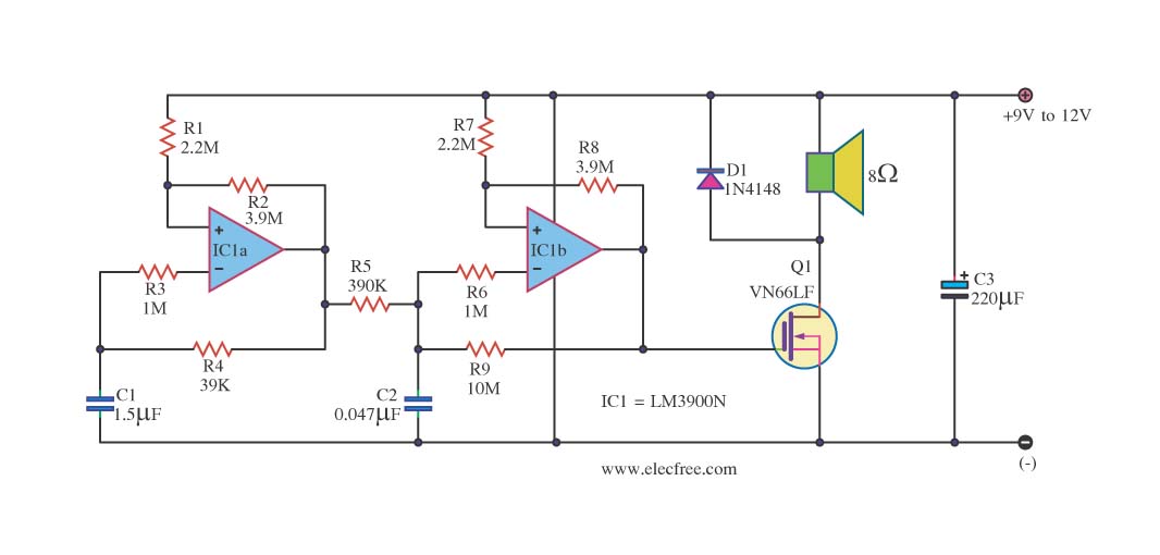
This circuit is a sound generator designed to create a super siren alarm signal using a live frequency generator circuit that incorporates an operational amplifier (op-amp). The circuit operates on the principle that when switch S1 is not pressed,...
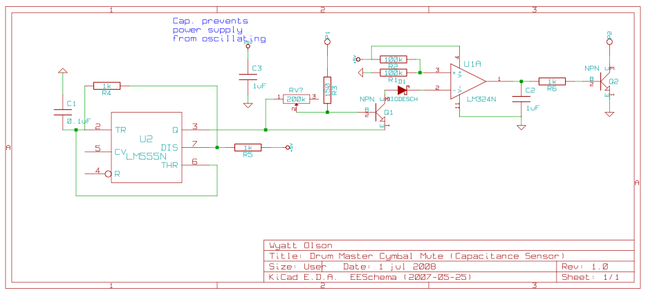
This page contains various small circuits created over time. Some circuits are trivial, while others are more complex, but all are intended to be useful for a variety of projects. Most include both the schematics and the source (KiCad)...
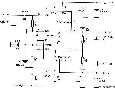
The TDA7294 is a monolithic integrated circuit housed in a Multiwatt15 package, designed to deliver high output power of up to 100W. It is intended for use as an audio Class AB amplifier in high-fidelity applications. The TDA7294 is a...
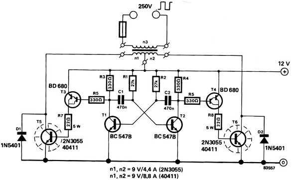
A power inverter converts direct current (DC) power to standard alternating current (AC) power. The following schematic illustrates a 12V power inverter circuit diagram. The 12V power inverter circuit typically consists of several key components that work together to achieve...
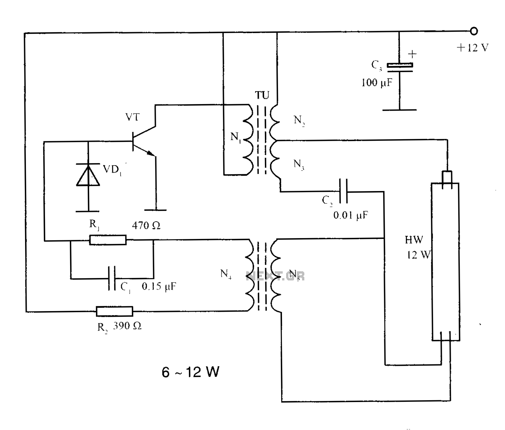
The lighting inverter circuit is designed for 6 to 12W fluorescent lamps. It operates by first bucking the mains voltage, followed by rectification and filtering to charge a battery. When the inverter is activated, it generates a high-frequency alternating...