
Police Car Lights with LEDs

The circuit utilizes an integrated circuit (IC1a), which is typically a 555 timer or similar, configured in astable mode to generate a continuous square wave output. The frequency of this square wave can be adjusted using a variable resistor (VR1), allowing for customization of the flashing rate to closely mimic the distinct pattern of police car lights.
The output from IC1a is fed into a driver stage, which may consist of transistors or MOSFETs, to amplify the signal and drive the high-power LED strobe lights. These LEDs are arranged in a manner that reflects the traditional layout of police lights, often in a dual-color configuration (e.g., red and blue) to enhance visibility and realism.
The circuit may also include additional components such as resistors to limit current to the LEDs, capacitors for smoothing and stability, and possibly diodes for protection against reverse polarity. A power supply circuit is essential to provide the necessary voltage and current levels for the operation of the IC and LED lights.
In summary, this circuit effectively replicates the visual effect of police car lights through the use of a square wave oscillator, adjustable frequency control, and a suitable driver stage to illuminate high-power LEDs, making it an excellent tool for educational purposes or for use in model displays.This circuit is used to simulate the police car lights by alternating flashing strobes seen on British police cars. The IC1a forms a square wave oscillator having adjustable frequency with VR1 to give the best effect.
This square wave is bu.. 🔗 External reference
Related Circuits

This amplifier is designed to be integrated with preamplifiers that lack a phono input. A phono input is essential for standard record players equipped with dynamic pick-ups, which remain widely used. The amplifier not only elevates the output of...
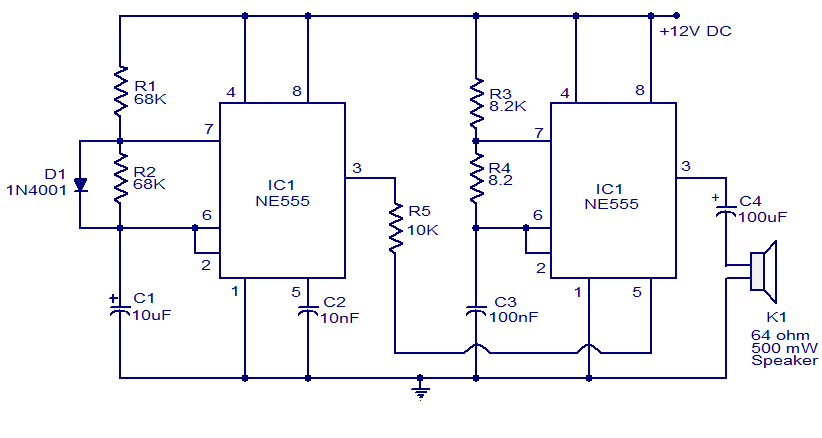
A variety of electronic circuits utilize the NE555 timer integrated circuit (IC). The circuit diagram presented illustrates a police siren based on two NE555 timer ICs, both configured as astable multivibrators. The circuit operates on a DC voltage supply...
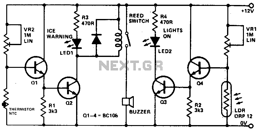
This device informs a driver whether their lights should be activated and warns them if the outside temperature approaches zero degrees Celsius by illuminating an LED and sounding a buzzer. The sensitivity can be adjusted using VR1, and the...
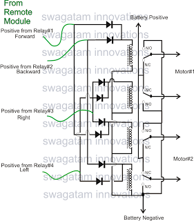
The market is filled with high-end remote-controlled toy cars; however, for hobbyists, creating one at home can be a unique experience. The following article explains how to configure a simple remote-controlled toy car using a pre-made 4-relay remote control...
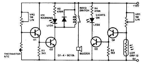
This electronic project circuit diagram for an ice warning and lights reminder system alerts drivers when their vehicle lights should be activated and warns them if the outside temperature approaches zero degrees Celsius. The system employs an LED indicator...

The circuit utilizes a 555 timer IC to create a lighting group delay effect, as illustrated in Figure 2-46. It consists of the 555 IC along with a resistor and capacitor configuration that establishes the delay. The circuit remains...