
Pontiac Fiero Wiring Diagram and Electrical System Schematic

The 1985 Pontiac Fiero features a complex electrical system designed to support various components and functionalities integral to vehicle operation. The wiring diagram serves as a comprehensive reference, illustrating the connections between different electrical components, including the battery, alternator, ignition system, lighting, and various sensors.
Key components of the electrical system include:
1. **Battery**: The primary power source for the vehicle, providing the necessary voltage for starting the engine and powering electrical accessories.
2. **Alternator**: Responsible for charging the battery while the engine is running, converting mechanical energy into electrical energy.
3. **Ignition System**: Comprising the ignition switch, coil, and spark plugs, this system is crucial for starting the engine and ensuring proper combustion.
4. **Lighting System**: This includes headlights, taillights, and interior lights, each with specific wiring configurations to ensure functionality and safety.
5. **Sensors**: Various sensors, such as those for the engine management system, provide critical data to the vehicle's electronic control unit (ECU) for optimal performance and fuel efficiency.
The wiring diagram includes color-coded lines representing different wire types and gauges, facilitating easy identification and troubleshooting. Each component is marked with specific codes that correspond to the vehicle's service manual, allowing technicians to diagnose issues effectively.
In summary, the 1985 Pontiac Fiero's electrical system is designed to provide reliable performance and safety features through a well-organized wiring diagram that aids in maintenance and repair activities.The following page outlines detail information and schematic of the 1985 Pontiac Fiero Wiring Diagram and Electrical System. The electrical system consists of: 🔗 External reference
Related Circuits

As shown in FIG XTR108, a four-wire RTD is connected to the circuit. In practical applications, the lead resistance of a four-wire RTD is typically not equal, which necessitates the use of a precision operational amplifier, OPA277, to minimize...
This precise one-pulse-per-second clock is constructed using a few common components and is powered by a 50 or 60 Hertz mains supply without any direct connection to it. A beep or metronome-like click, along with a visible flash, indicates...
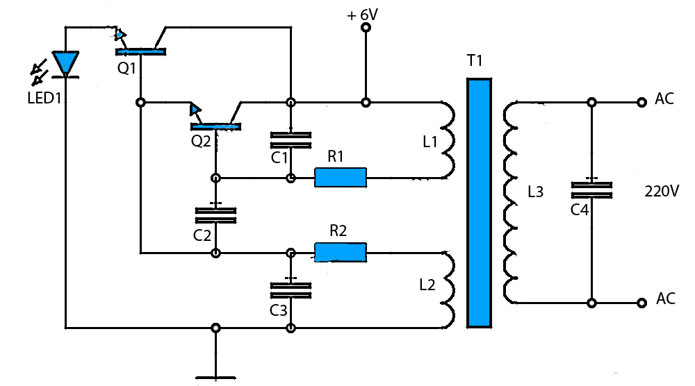
The circuit schematic presented is a voltage inverter circuit that converts a 6-volt DC input into a 220-volt AC output. It is designed to deliver a maximum output power of 30 watts and operates with a low input current....
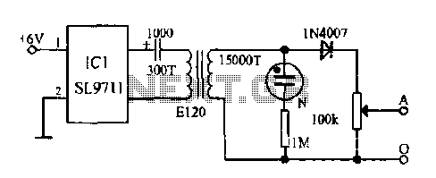
The electronic frostbite treatment instrument ASIC SL9711 consists of an oscillation circuit, a power amplifier, and a controller. It generates a sine wave at frequencies of 100 Hz and 3 Hz, followed by a step-up transformer with potentiometer adjustment...
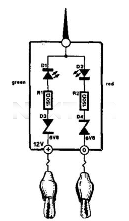
This compact tester is designed for checking vehicle electrical circuits. Two LEDs indicate whether one of the clips is connected to the positive supply line (red) or to ground (green). The unit is powered by the vehicle battery. It...
The circuit is divided into two sections: the isolated external loop connected to the remote interface connector on the front of the power supply unit (PSU) and the non-isolated inner loop connected to the high-tension (AC line) supply. The...