
6V to 220V inverter schematic Schematic Diagram

The voltage inverter circuit operates by utilizing a transistor as a switch to control the flow of current through the transformer. The 6-volt DC input is fed into the base of transistor Q2, which is configured in a common-emitter arrangement. When the base voltage exceeds the threshold, Q2 conducts, allowing current to flow from the collector to the emitter. This action induces a magnetic field in the transformer, which in turn generates a higher voltage at the secondary winding, producing the desired 220-volt AC output.
Inductor L1 plays a crucial role in the feedback mechanism, providing necessary base current to maintain the transistor's operation. The design ensures that the transistor operates in a switching mode, allowing for efficient energy transfer and minimizing heat generation. Inductor L2 is used to stabilize the voltage supplied to the emitter, ensuring consistent operation of the circuit under varying load conditions.
The inclusion of LED1 is an essential feature for user feedback, as it visually indicates the operational status of the inverter. When the circuit is active and Q2 is conducting, LED1 illuminates, confirming that the inverter is functioning correctly. This feature is particularly useful for troubleshooting and monitoring the inverter's performance.
Overall, this voltage inverter circuit is compact and efficient, suitable for applications requiring a modest power output while converting low-voltage DC to high-voltage AC. It is important to ensure that all components are rated appropriately for the expected voltage and current levels to maintain reliability and safety during operation.Circuit schematic above is one of the voltage inverter circuit, starting from 6-Volt input on the DC current into 220-volt AC output. For maximum output power up to 30W only, and is also very small voltage current. Input voltage plus the entrance on the transistor Q2 to provide the voltage at the collector and then go on Circumference transformer
L1 and enter the base. Emitter will be merged ddengan voltage supplied L2 min. And LED 1 is useful as an indicator of whether or not an inverter works especially on the transistor Q2. 🔗 External reference
Related Circuits
The circuit in the diagram generates a negative voltage without using integrated circuits. It utilizes five n-p-n transistors driven by an approximately 1 kHz TTL clock. When the clock input is high, transistors T1 and T2 connect capacitor C1...
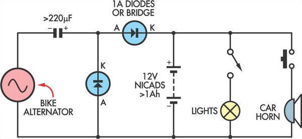
This simple circuit enables a 12V battery pack to be charged using a bike generator. The generator is rated at 3W and, with the inclusion of a voltage multiplier circuit, delivers approximately 200mA at a speed of around 15...
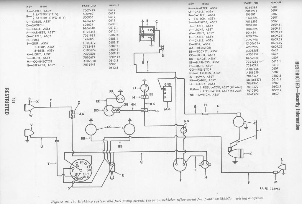
The circuit diagram presented here pertains to the electrical wiring of the 1986 Ford Bronco and F-Series Pickup. It is essential to thoroughly read and understand the electrical wiring diagram before making any modifications to the wiring of these...
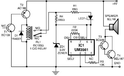
This heat detector alarm electronic project is designed using the UM3561 sound generator circuit along with several common electronic components. The heat detector circuit employs a complementary pair of transistors, consisting of an NPN and a PNP transistor, to...
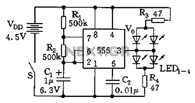
The circuit consists of a 555 timer and a light-emitting diode (LED) array. The 555 timer, along with resistors R1, R2, and capacitor C1, forms an astable multivibrator configuration. The oscillation frequency is calculated using the formula f =...
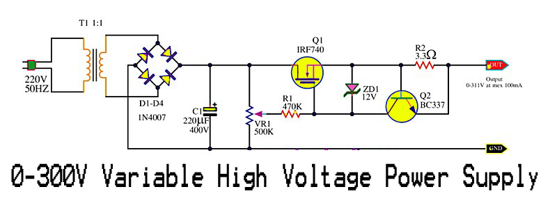
This is a variable high voltage DC power supply circuit that allows for customization of the output voltage ranging from 0 to 311V DC. It includes a current limit protection feature set at approximately 100 mA. The power MOSFET...