
Ponyprog Circuit for ATMEL AVR

The ATMEL AVR programmer is a device designed for programming AVR microcontrollers. It interfaces with the microcontroller through the ISP (In-System Programming) method, allowing users to upload firmware directly onto the chip without the need for an external programmer. This feature is particularly useful for development and debugging purposes.
Ponyprog is a widely used software tool that facilitates the programming process. It provides a user-friendly interface for writing and reading data from the microcontroller's memory. The software supports various programming modes and configurations, making it adaptable for different applications. Users can access features such as EEPROM programming, flash memory writing, and fuse bit settings, which are essential for customizing the microcontroller's behavior.
The ATMEL AVR programmer connects to a computer via a standard interface, typically USB or serial port, depending on the specific model. The programmer is powered through the connection to the computer, eliminating the need for an external power supply.
For successful operation, it is essential to ensure that the correct drivers are installed on the Windows operating system. Compatibility with older Windows versions, such as 95, 98, and XP, allows a broader range of users to utilize the programming tool, although it may limit the use of modern features and updates available in newer operating systems.
In summary, the ATMEL AVR programmer in conjunction with the Ponyprog software provides a robust solution for programming AVR microcontrollers, enabling efficient development and testing of embedded systems.The ATMEL AVR programmer works with the Windows program ""Ponyprog"" which works under 95, 98, XP. 🔗 External reference
Related Circuits
The bi-directional sequencer utilizes a 4-bit binary up/down counter (CD4516) and two "1 of 8 line decoders" (74HC138 or 74HCT138) to create the well-known "Night Rider" display. A Schmitt Trigger oscillator generates the clock signal for the counter, with...
This analog switch circuit is designed to switch an analog line on or off. It consists of two analog switches in integrated circuit (IC) form that are controlled by two pushbuttons. The described analog switch circuit utilizes two integrated analog...
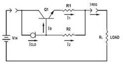
This application datasheet article includes sections that discuss the practical current booster circuit technique, which involves a conventional circuit using a Constant Current Load (CLD) and a current boosting circuit technique. It covers the analysis of the booster circuit...
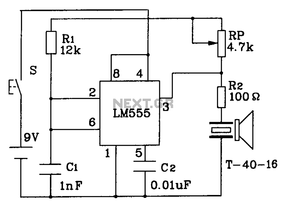
The circuit described is a 555 ultrasonic transmitter constructed to emit ultrasonic signals at a frequency of 40 kHz. It operates by generating oscillating pulse outputs from a 555 timer (specifically the T-40-16 model). The circuit is designed to...
This is a circuit diagram of a simple circuit in which the LED can be activated only by a gust of air. A condenser microphone (M1) is used to detect breath. When the S1 button is pressed, transistors Q2...
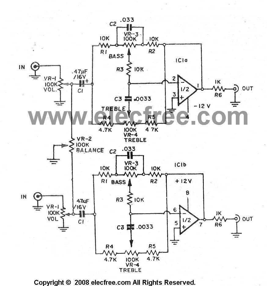
A high-quality preamplifier with tone controls consisting of three circuits. The NE5532 is chosen as the main integrated circuit due to its ultra-low noise properties, making it a popular choice in fine audio applications. Although these circuits are older...