
puff to off circuit

The circuit operates primarily through a combination of a condenser microphone, transistors, and an LED. The condenser microphone (M1) serves as a sensor that converts sound waves, specifically the breath of a user, into an electrical signal. This signal is typically a low-level voltage that needs amplification to be effective in controlling other components of the circuit.
Transistor Q1 functions as an amplifier. When the microphone detects a breath, it generates a voltage signal, which is fed into the base of Q1. As the sound pressure increases, the output voltage from the microphone rises, causing Q1 to conduct more current. This results in a higher voltage at the collector, which is then coupled to the emitter of the transistor pair Q2 and Q3.
Transistors Q2 and Q3 are configured in a push-pull arrangement. When the S1 button is pressed, it provides the necessary biasing to turn on Q2 and Q3. This allows current to flow from the power supply through the LED, illuminating it. The LED remains on as long as Q2 and Q3 are activated.
However, once the breath signal dissipates and the voltage from the microphone falls below a certain threshold, Q1 stops conducting, which in turn deactivates Q2 and Q3. This results in the LED turning off. To reactivate the LED, the user must press the S1 button again, resetting the circuit.
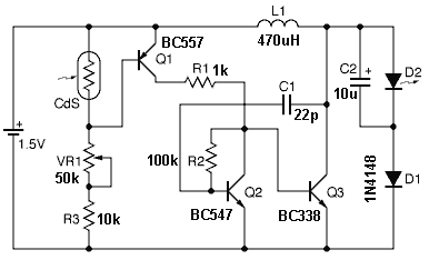
The design of this circuit emphasizes a simple yet effective method of controlling an LED based on sound pressure, showcasing the use of basic electronic components such as microphones, transistors, and LEDs in a straightforward application. The schematic would typically illustrate the connections between these components, including the power supply, the microphone, the various transistors, and the LED, ensuring clarity in how the circuit operates as a whole.This is a circuit diagram of a simple circuit in which the LED burning can be activated only by a gust OFF. A condenser mic (M1) is used to feel your breath. When the S1 button is pressed, transistors Q2 and Q3 as a couple wires attached will be activated and drives LED shines.
LED remains in this condition. When you puff on a condenser mic, the s ound pressure converted into a voltage signal at the output. This voltage signal is amplified by the transistor Q1. Since collector of Q1 coupled to the emitter of the pair attached, the couple will stop doing as there ever was a signal from a condenser mic for panting and the LED will go OFF. Push button switch S1 should be pressed again to turn the LED ON. The following is a schematic drawing: 🔗 External reference
Related Circuits
It is essential to draw a circuit using a layout and conventions that are universally recognized. In electronic circuit design, adherence to standardized symbols and layout conventions is crucial for effective communication among engineers and technicians. A well-drawn schematic diagram...
This TDA2030 35-watt audio amplifier circuit project is designed to deliver an output power of 35 watts into an 8-ohm load. The TDA2030 is a monolithic integrated circuit housed in a Pentawatt package, intended for use as a low-frequency...
This circuit functions as an RF power amplifier designed to operate with a power supply capable of delivering 13 volts at a current of 10 amperes. Careful assembly of the power source is essential. It utilizes a shielded transformer...
The circuit consists of a light metering circuit and a flash circuit, as illustrated in the accompanying image. It is designed for use with integrated cameras such as POPTICS, Franka X-500, and WIZEN-860S. The circuit includes the following components:...
The figure illustrates a schematic for an oscillator amplitude-control servo system. The circuit establishes a closed-loop system that provides a fixed and adjustable peak-to-peak amplitude AC signal centered around 0 V. A 1 kHz sine wave, designated as AC_INPUT,...
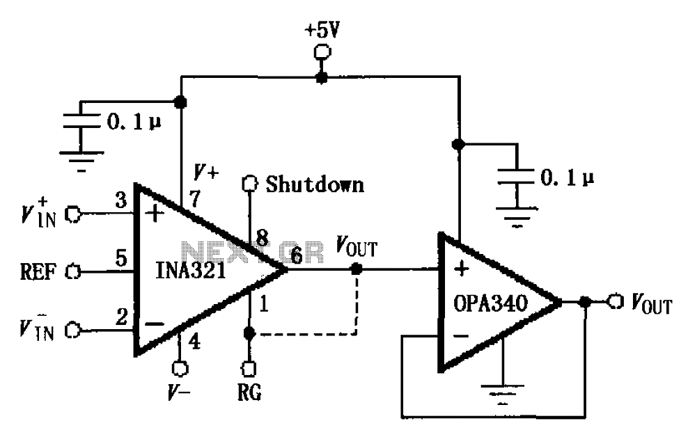
The circuit depicted in the figure consists of an OPA340 operational amplifier configured as a voltage follower, serving as an output buffer for the INA321/322 output. The optimal load impedance for the INA321/322 is 10k ohms or greater. A...