
Ponyprog for AVR & PIC16F84

MICROCHIP's PIC series
PIC16x83, PIC16x84, PIC16F84A
And some other programmable ICs (memories, microcontrollers) which Ponyprog supports but need a board adapter to be programmed through ISP connectors. For more information see Claudio Lanconelli's site.
The described circuit is a versatile programming interface designed to facilitate the programming of various microcontrollers from both Microchip and ATMEL. The power supply for the circuit operates within a range of 9 to 15 volts, accommodating both DC and AC inputs, which enhances its usability in diverse applications. The use of 1/4W resistors throughout the circuit ensures that power dissipation remains manageable, maintaining the integrity and reliability of the components.
The inclusion of In Circuit Programming (ISP) connectors allows for direct programming of the microcontrollers while they are mounted on the PCB, which is a significant advantage for development and testing purposes. The circuit is designed to allow the programmer to draw power from the target device, thereby eliminating the need for an external power source when the target is powered on. This feature is safeguarded by diodes D2 and D6, which protect the LM7805 voltage regulator from potential backflow of current, ensuring stable operation.
The "PIC JUMP" functionality provides a practical means to switch between programming Microchip's PIC microcontrollers and ATMEL's microcontrollers. By setting the jumper to the ON position, the circuit is configured to program only PIC devices, while switching to the OFF position enables programming of ATMEL microcontrollers. This dual functionality increases the circuit's versatility and utility for developers working with different microcontroller families.
For flexibility in component placement, the PCB has been designed to accommodate both Dual In-line Package (DIP) sockets and Zero Insertion Force (ZIF) sockets. The recommendation to use a single ZIF socket paired with pin arrays for switching between different microcontroller positions is a cost-effective solution that optimizes space and reduces complexity on the board.
The circuit supports a wide range of microcontrollers from both manufacturers, including various models from the ATtiny and ATmega series by ATMEL, as well as multiple models from Microchip's PIC series. This broad compatibility makes the circuit a valuable tool for developers and engineers involved in microcontroller-based projects. Additionally, the mention of other programmable ICs that may require board adapters for ISP programming indicates the circuit's potential for further expansion and adaptability in various programming scenarios.All resistors are 1/4W.The circuit is powered by 9...15V DC or AC. When In Circuit Programming (ISP) connectors are used, is possible the programmer to be powered from target?s power source. Diodes D2 and D6 protect the regulator LM7805, when target?s power is used. ?PIC JUMP? is used to switch between Microchip?s PIC and ATMEL?s microcontrollers. With jumper ON only PIC can be programmed, while OFF can program ATMEL?s microcontrollers. If you don?t need to program PICs, you can leave their board area unsoldered. The PCB has been designed so that DIP sockets or ZIF sockets can be used. Because of its cost, it is recommended that only one ZIF is used combined with some pin-arrays to switch between the four different places.
ATtiny12, ATtiny15, AT90S1200, AT90S1200A, AT90S2233, AT90S2313, AT90S2323, AT90S2343, AT90S4414, AT90S4433, AT90S4434, AT90S8515, AT90S8535, ATmega8, ATmega16, ATmega161, ATmega163, ATmega323, ATMEL?s 8051 series, AT89S53, AT89S8252 MICROCHIP?s PIC series PIC16x83, PIC16x84, PIC16F84A And some other programmable ICs (memories, microcontrollers) which Ponyprog support but need a board adapter to be programmed through ISP connectors. For more information see Claudio Lanconelli site . 🔗 External reference
Related Circuits
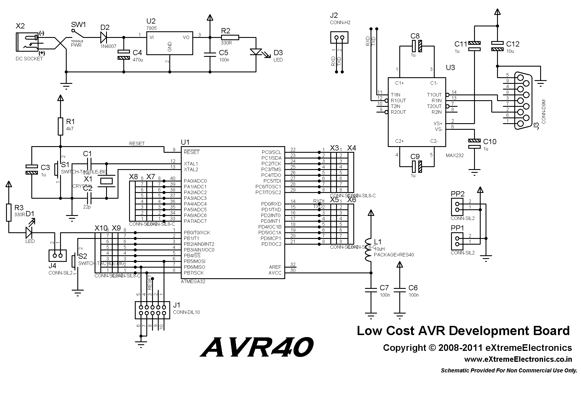
This low-cost AVR development board is designed for beginners to work with 40-pin AVR devices, facilitating easy testing and project development. When paired with a USB AVR Programmer, it serves as a comprehensive development and learning platform. The included...

The ATR0981 is a monolithic integrated circuit (IC) produced using Atmel's advanced SiGe technology. This IC serves as a transmit and receive front-end solution, specifically designed for operation within a frequency range of 300 MHz to 500 MHz. It...
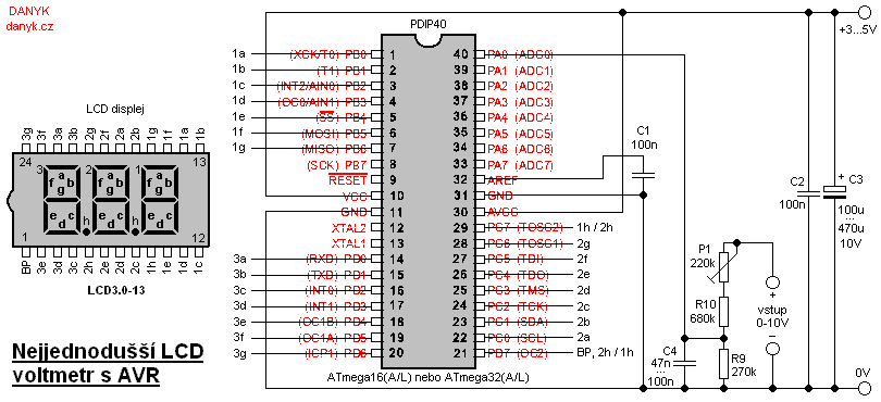
This is likely the simplest digital voltmeter utilizing an Atmel AVR microcontroller and an LCD display. The circuit is managed by a microprocessor IO1 - AVR Atmel ATmega16A, ATmega16L, ATmega16, ATmega32A, or ATmega32. A program is available for free...
The following circuit diagram illustrates a very simple AVR microcontroller setup (source: unknown). It requires minimal components and is easy to construct on a general-purpose matrix PCB. PonyProg2000 software can be used to program the AVR microcontroller with this...
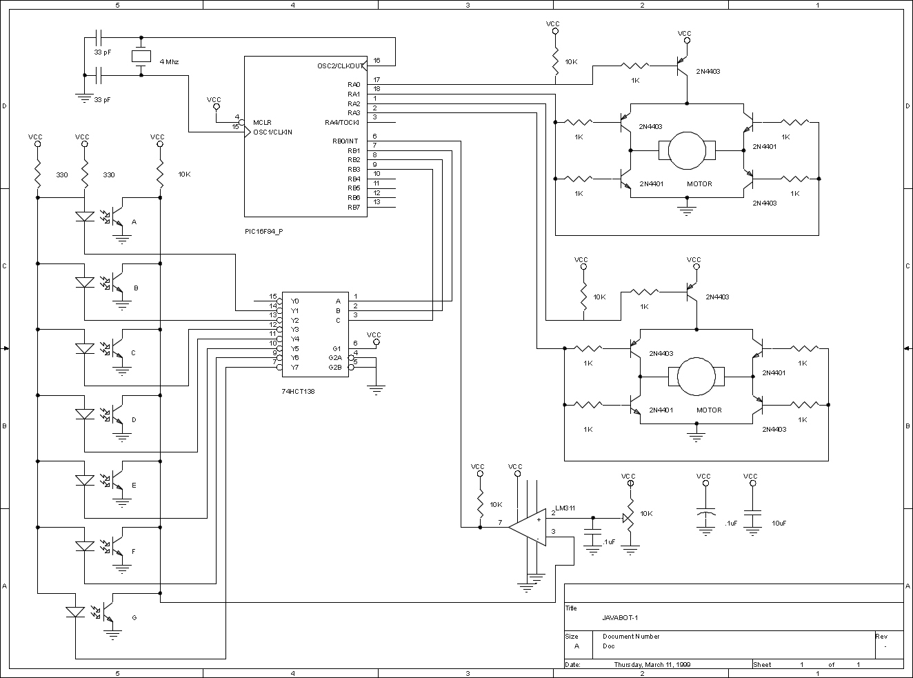
The JavaBot1 is a compact line-following robot engineered to trace a black line drawn on a dry erase board. It is specifically designed to navigate along very narrow curves. The JavaBot1 employs a differential drive mechanism, which allows it to...
This scanner uses a DDS circuit to scan through the frequency band. Since a DDS is used to set the desired frequency, this receiver can jump from one frequency to another within microseconds, making it very fast. The receiver...