
Accu charger use a diac and triac Schematic Diagram

The described circuit serves as an efficient battery charger for accumulator and cell batteries, utilizing a diac and triac configuration to enhance performance. The stability of the output voltage is crucial for prolonging battery life, as it prevents overcharging and ensures that the battery is charged within its optimal voltage range. The use of a diac in the gate circuit provides precise control over when the triac is triggered, ensuring that the charging process is initiated only when the input voltage exceeds a specific threshold. This mechanism helps to prevent potential damage to the battery from excessive current.
The transient suppression network, consisting of capacitor C3 and resistor R4, is essential for protecting the circuit from voltage spikes that could arise during the charging process. This network absorbs sudden changes in voltage, thereby safeguarding both the charger and the battery from potential harm.
The phase-shift network formed by resistors R1, R2, R3, and capacitors C1 and C2 plays a critical role in shaping the signal that is applied to the gate of the triac. This network is designed to ensure that the triac operates efficiently, allowing for smooth control of the charging current. Specifically, resistor R1 limits the maximum charging current when the adjustment potentiometer R2 is at its maximum setting, which is vital for preventing overheating and ensuring safe operation during the charging cycle.
Overall, this circuit design emphasizes stability, safety, and efficiency, making it an effective solution for charging accumulator and cell batteries.This circuit can be used to charge Accu and cells battery, the circuit can has a very stable output that would make the battery last longer and maximize the added battery capacity. When charge was also quite fast, so it can optimize the time. A diac is used in the gate circuit to provide a threshold level for firing the triac. C3 and R4 provide a transient suppression network. R1, R2, R3, C1, and C2 provide a hase - shift network for the signal being applied to the gate. R1 is selected to limit the maximum charging current at full rotation of R2. You are reading the Circuits of Accu charger use a diac and triac And this circuit permalink url it is 🔗 External reference
Related Circuits
This document contains a collection of various useful and interesting electronic schematics. Some of these schematics are referenced or included in other documents on this site. Notably absent from this collection is extremely important safety information, which can be...

This circuit utilizes three readily available 555 timer integrated circuits (ICs), all functioning as astable multivibrators. The first 555 timer has both an on period and an off period of 1 second. This IC regulates the on/off intervals of...
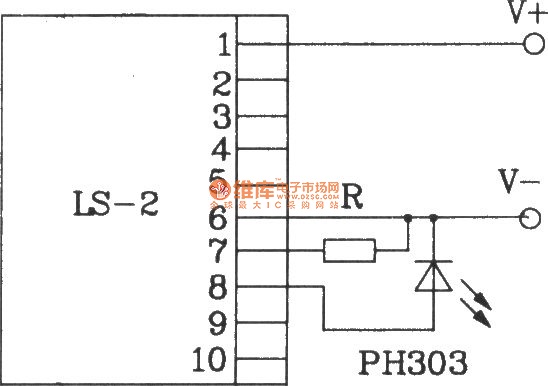
The LS-2 remote control switch infrared sensor module is similar to the LS-18 but functions as a reflector. The LS-2 pin diagram and internal block diagram provide insights into its electrical parameters. The operating voltage for the LS-2 remote...
Due to the small size, high precision, and sensitivity of surface acoustic wave (SAW) sensors, along with their cost-effectiveness, a SAW gas sensor has been developed. This sensor comprises a surface acoustic wave device, a sensitive membrane, and the...
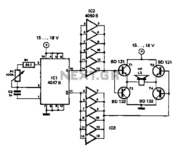
A low-cost and straightforward repellent circuit can be utilized for deterring rats, mice, and other animals, as illustrated in the electronic figure below. The circuit employs a CMOS integrated circuit of type 4047, which functions as a relaxation oscillator....
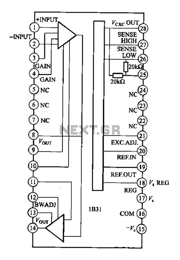
The Analog Devices 1831 is designed for strain gauge signal conditioning applications. It features an internal low drift input of 0.25V with a gain of 1000, exhibiting excellent linearity with a maximum deviation of 0.005%. The IC operates with...