
Portable Mixer

The circuit design focuses on minimizing noise while providing adjustable gain, making it suitable for various audio applications, particularly in professional audio setups. The variable gain feature allows for flexibility in handling different microphone sensitivities or line levels, ensuring optimal performance across a range of input sources.
The Tone Control Module enhances the audio signal by allowing users to adjust frequency bands independently, which can be crucial for tailoring sound to specific environments or personal preferences. The three-band equalization helps in managing the tonal balance of the audio output, facilitating a more polished sound.
The block diagram provides a clear representation of the system architecture, indicating how each component interacts within the mixer. The inclusion of multiple Input Amplifier Modules allows for the simultaneous processing of several audio sources, while the in-out switchable Tone Control Modules provide further customization options. The layout is designed to streamline the mixing process, with intuitive controls such as the Main Faders and Pan-Pots, which allow for precise adjustments to the audio mix.
The use of a stereo dual-gang 100K potentiometer for the stereo line input ensures smooth fading capabilities, allowing for seamless transitions between audio sources. The pilot light LED serves as a visual indicator of the system's operational status, enhancing user experience. Additionally, the DPDT switches provide the flexibility to bypass the Tone Control Modules when desired, making the system versatile for various applications.
This comprehensive design reflects a well-thought-out approach to audio mixing, incorporating essential features that promote high-quality sound reproduction and user-friendly operation.A low noise circuit equipped with a variable voltage-gain (10 - 100) pre-set, primarily intended as high quality microphone input, also suitable for low-level line input. Tone Control Module: a three-band (Bass, Middle, Treble) tone control circuit providing unity-gain when its controls are set to flat frequency response.
It can be inserted after one or more Input Amplifier Modules and/or after the Main Mixer Amplifiers. The image below shows a Block diagram of the entire mixer featuring four Input Amplifier Modules followed by four in-out switchable Tone Control Modules, one stereo Line input, four mono Main Faders, one stereo dual-ganged Main Fader, four Pan-Pots, a stereo Main Mixer Amplifier Module and two further Tone Control Modules switchable in and out for each channel, inserted before the main Left and Right outputs. To parts listed above should be added: one Main on-off SPST switch, a LED used as pilot-light with its dropping 2K2 1/4W series-resistor, DPDT switches to enable or omit Tone Control Modules as shown in the Block diagram, input and output connectors of the type preferred, one stereo dual-gang 100K potentiometer to fade the Stereo Line Input as shown in the Block diagram, battery clip, PP3 9V battery, knobs etc.
🔗 External reference
Related Circuits
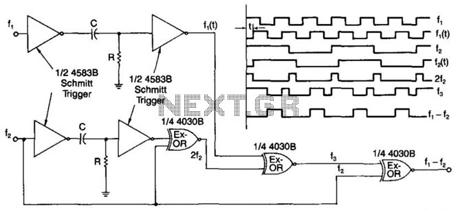
A simple digital mixer uses two dual-Schmitt triggers (4583B) and three exclusive-OR gates, incorporating an RC time-delay circuit to allow for easy adjustment of the output signal pulse width. The exclusive-OR gates can also function independently as a symmetrical...
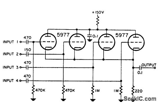
This circuit is utilized for combining four distinct positive-polarity marker pulses in a radar system. The reference for this information is the "Handbook Preferred Circuits Navy Aeronautical Electronic Equipment," Volume 1, Electron Tube Circuits, published in 1963, page N4-1. The...
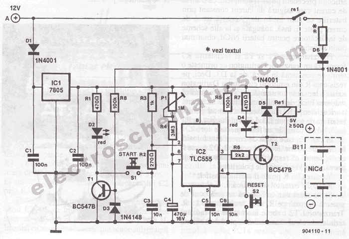
The portable battery charger has been designed to enable the charging of NiCd batteries outdoors using a 12 V vehicle battery. The portable battery charger is engineered to facilitate the charging of Nickel-Cadmium (NiCd) batteries in outdoor environments, leveraging the...
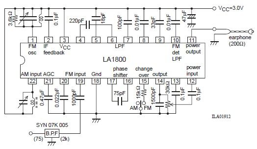
This portable AM/FM radio circuit is designed using the LA1800 integrated circuit (IC) along with several external components. The LA1800, manufactured by Sanyo Semiconductors, requires only a few additional components for its operation. The output signal is directed to...
A simple half-wave motor speed control circuit is effective for small universal AC/DC motors, with a maximum current capability of two amps RMS. The half-wave motor speed control circuit utilizes a diode to allow current to flow in only one...
This weblog focuses on electronic circuit schematics, PCB design, DIY kits, and diagrams for various electronic projects. It features a mixer that demonstrates how to create microphone pre-amplifiers suitable for both low and high impedance microphones. The design utilizes...