
Portable Solar Lantern

The portable solar lantern circuit is designed to harness solar energy through a 6 volt/5 watt photovoltaic panel, converting sunlight into electrical energy to power the lantern. The circuit typically includes several key components: the solar panel, a rechargeable battery, a charge controller, an LED light source, and a housing structure.
The solar panel serves as the primary energy source, generating electricity when exposed to sunlight. The generated voltage is used to charge a rechargeable battery, such as a lead-acid or lithium-ion battery, which stores energy for use when sunlight is not available. The charge controller is an essential component that regulates the voltage and current coming from the solar panel to prevent overcharging and ensure the battery operates within safe parameters.
The LED light source is chosen for its energy efficiency and long lifespan, providing illumination with minimal power consumption. The circuit may also include a switch to turn the lantern on and off and possibly a dimming feature to adjust brightness levels based on user preference.
The housing structure is designed to be portable and durable, allowing the lantern to be used in various outdoor environments. It is typically weather-resistant to protect the electronic components from moisture and dust. The overall design emphasizes ease of use, portability, and sustainability, making it an ideal solution for outdoor activities, emergency lighting, or as a reliable source of light in off-grid situations.
In summary, this portable solar lantern circuit represents an effective application of renewable energy technology, providing a practical and eco-friendly lighting solution.This portable solar lantern circuit uses 6 volt/5 watt solar panels are now widely available. With the help of such a photo-voltaic panel we can construct.. 🔗 External reference
Related Circuits
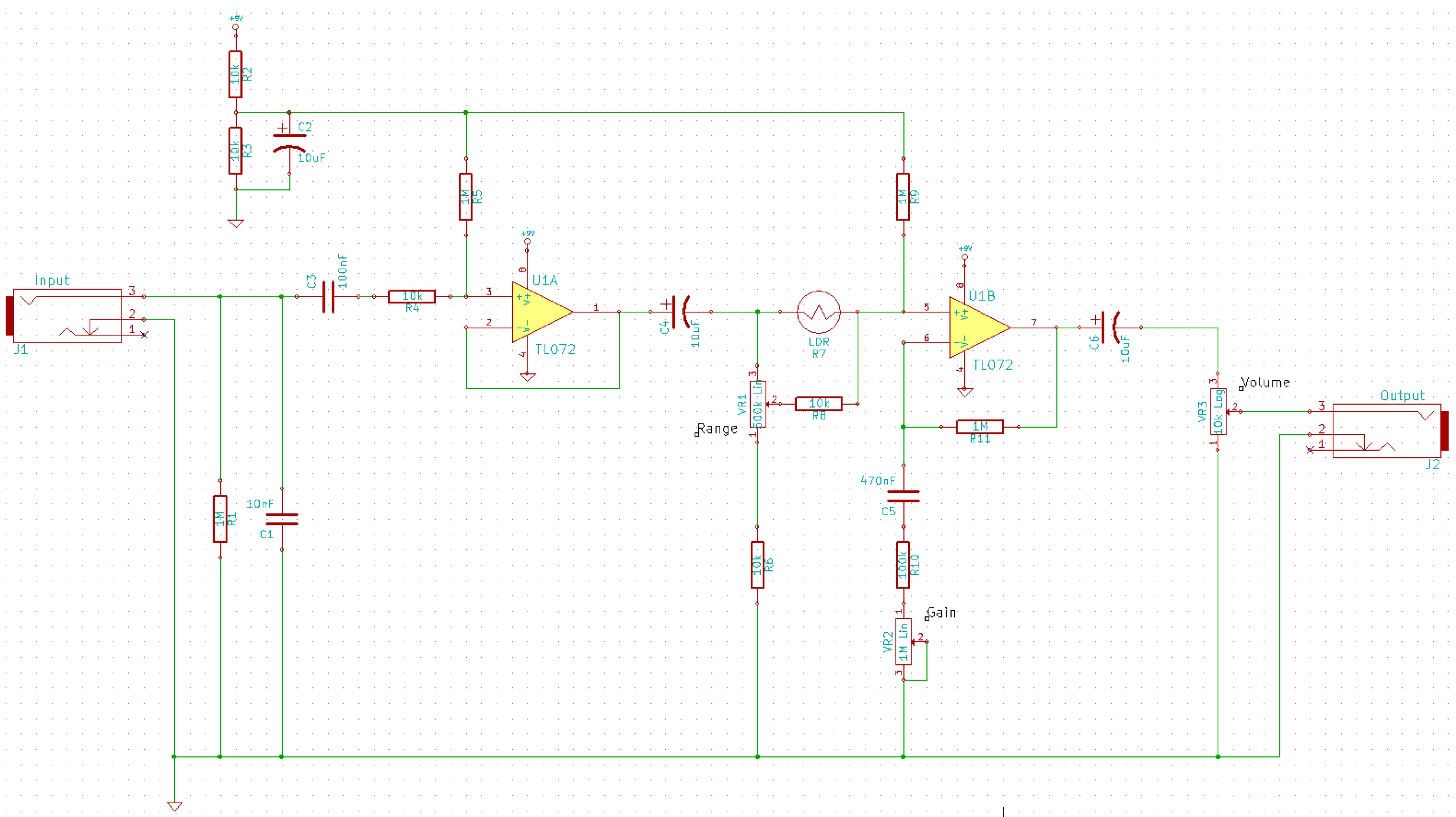
This is a simplified schematic for the Solar Lifeforce. The design eliminates the expression/CV output features and the toggle for the buffer, making it a straightforward circuit. It may benefit from adding small capacitors between R5 and ground, as...
This file is copyrighted. The individual who uploaded this work and first used it in licensing holds the rights. The provided information indicates that the file is protected by copyright, with the rights belonging to the individual who initially uploaded...
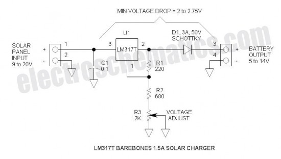
This is the simplest and most affordable solar battery charger that a hobbyist can create. It has some drawbacks compared to other similar controls, but offers unique advantages. The solar battery charger circuit is designed to harness solar energy to...
This circuit is designed to charge NiCd or NiMH batteries using solar cells. It maximizes power extraction from a solar array to charge a battery stack. The circuit utilizes the MAX856 boost converter and the MAX982 dual comparator with...
The capacitor charges until the PNP transistor (here shown as a 2N3906, but you could also use a BC327) receives base current through the Zener and turns on. Then the NPN transistor (here shown as a 2N3904, but you...
The previous version of this device used pulse width modulation (PWM) to control the power from the five solar panels to charge the battery bank. Under full sun conditions, the MOSFETs got a bit warm and the whole unit...