
Solar Tracker circuit schematic
The provided information indicates that the file is protected by copyright, with the rights belonging to the individual who initially uploaded and utilized the work. In the context of electronic schematics or designs, copyright protection is crucial as it ensures that the intellectual property associated with the design remains safeguarded against unauthorized use or reproduction.
In electronic design, copyright applies to the schematic diagrams, layout designs, and any associated documentation that outlines the functionality and construction of electronic circuits. This protection allows the creator to control how their designs are used, distributed, and modified. It is essential for engineers and designers to understand the implications of copyright in their work, particularly when collaborating on projects or sharing designs within the industry.
When creating or utilizing electronic schematics, it is advisable to include clear licensing statements that define the terms under which the work can be used by others. This can encompass various forms of licensing, such as open-source licenses, which allow for broader use and modification, or more restrictive licenses that limit the distribution and alteration of the work.
In summary, the copyright status of electronic schematics is a critical aspect that impacts how designs are shared and utilized within the engineering community, ensuring that the rights of the original creators are respected and upheld. Licensing This file is copyrighted. The individual who uploaded this work and first used it in Licensing This file is copyrighted. The individual who uploaded this work and first used it in Licensing This file is copyrighted. The individual who uploaded this work and first used it in ","0",.. 🔗 External reference
Related Circuits
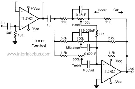
This topic continues the coverage of audio tone controls. The first entry started with a passive tone control circuit using different RC filter configurations and introduced an active filter. The second entry showed a fully designed 2-band active tone...
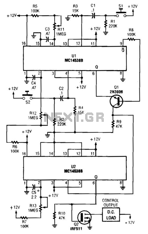
When switch SI is closed, pin 9 of operational amplifier U1 goes low, activating transistor Q1 for a predetermined duration. If switch S2 is closed during this time, transistor Q2 is activated for another predetermined duration. Resistors R1 and...
Connect the diode VD under test to sockets X1 and X2. A stabilized power supply applies reverse breakdown voltage to VD, allowing the stabilized voltage value Uz to be read from voltage meter V. The stable operating current value...
This is a simple and cost-effective inverter designed to power a small soldering iron (25W, 35W, etc.) when a mains supply is not available. The circuit utilizes eight transistors along with several resistors and capacitors. Transistors Q1 and Q2,...
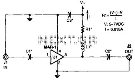
The low-cost Mini-Circuits MAR-X series of chips provides a significant advantage for RF builders, featuring inherent 50-ohm input and output impedances essential for RF systems. An MAR-1-based receiver/scanner preamplifier is illustrated. Capacitors Ci and C2 are chip capacitors, with...
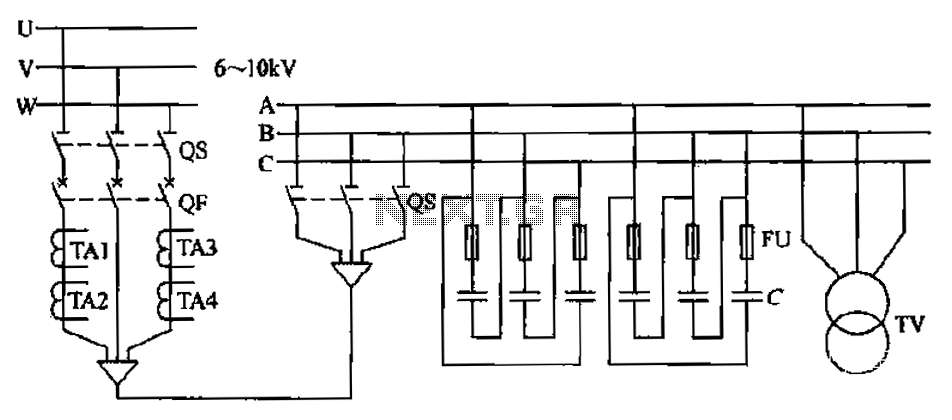
The compensation system is designed to focus on a high-pressure, high-voltage capacitor bank installed in the substation 6-10 kV bus. Compensation can only be implemented in this manner for the 6-10 kV bus before the reactive power on the...