
POT-PLANT POWER

The phenomenon of plants carrying an electric charge can be explored through a circuit that measures this voltage. A basic schematic can be designed to facilitate this measurement. The circuit consists of a few key components: a voltmeter, a pair of electrodes (the chrome-plated pin and the iron spike), and optional amplification circuitry to enhance the signal for more precise readings.
In the schematic, the positive terminal is represented by the chrome-plated pin, which is inserted into the plant tissue. This pin serves as the point of contact to measure the plant's electric potential. The negative terminal is represented by the iron spike, which is driven into the ground, providing a reference point for the measurement.
The voltmeter is connected across these two terminals, allowing for the measurement of the voltage difference between the plant and the ground. Depending on the design, an operational amplifier (op-amp) can be included in the circuit to amplify the small voltage signal obtained from the plant, making it easier to read on the voltmeter. The op-amp should be configured in a non-inverting mode to ensure that the output voltage is proportional to the input voltage.
For added protection and accuracy, resistors may be included in the circuit to limit current and prevent damage to the measuring instruments. Additionally, a capacitor can be placed in parallel with the voltmeter to filter out any high-frequency noise that may interfere with the readings.
This simple yet effective circuit allows for the observation and study of the electric charge present in plants, providing insights into their physiological state and the potential effects of environmental factors on their electrical properties. Further research could explore the implications of these findings in fields such as agriculture, botany, and bioelectronics.Following a hunch, the author discovered (or re-discovered?) that all plants carry an electric charge relative to the ground. This charge is more or less constant regardless of the size of the plant - a kind of "background voltage" in nature.
This electric charge suffuses the entire plant, from its roots to its leaves and fruit. It was measured between a chrome-plated pin inserted into the plant (the positive terminal) and an iron spike driven into the ground (the negative terminal). 🔗 External reference
Related Circuits

Designing a power supply that meets the requirements of Power over Ethernet (PoE) and Voice over Internet Protocol (VoIP) applications can be complex. The low-component-count power supply illustrated in the figure complies with these specifications without requiring intricate circuitry....
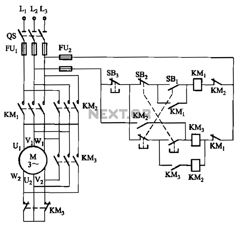
A hoist rated at 22kW and below is equipped with a power-saving Y-conversion circuit, as depicted in the figure. This circuit enhances the standard hoist design by incorporating a CJ20-10A exchange contactor. The implementation of the Y-conversion circuit during...
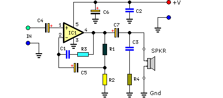
This compact amplifier is built around the TDA2003 integrated circuit, which can deliver 4W RMS at a 4-ohm load. The TDA2003 offers enhanced performance while maintaining the same pin configuration as the TDA2002. It retains the advantageous features of...
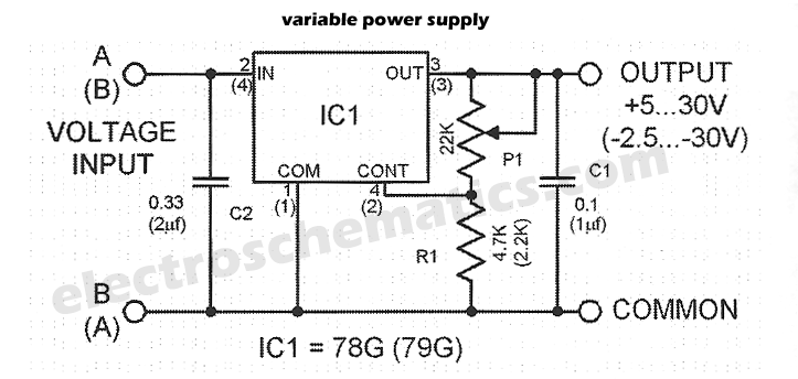
Four simple 12V power supply circuits are designed to provide output voltages close to 12V. The first power supply circuit utilizes a BD139 transistor, a zener diode, and several passive components. Each schematic is straightforward to assemble and will...
Here are some utility circuits for use with the Ramsey FM10a, and other small FM stereo transmitter kits. This information may be helpful for setting up a micro powered FM radio station. The FM10a and similar kits tend to...
The CD4069 unit structure depicted in Figure 2-5 (a) consists of two abutment surfaces incorporated into a CMOSFET configuration. The input-output characteristics are illustrated in Figure 2-5 (b). Due to its superior unit switching curve, the CD4069 can be...