
12V Power Supply Circuits

The first circuit employs the BD139 transistor as a voltage regulator. It is configured in a common-emitter arrangement, where the zener diode is used to establish a stable reference voltage. The zener diode is connected in reverse bias across the base-emitter junction of the transistor, which ensures that the output voltage remains regulated at approximately 12V. The choice of the zener diode's breakdown voltage is critical, as it determines the output voltage stability.
In addition to the BD139 and zener diode, passive components such as resistors and capacitors are included in the design. The resistors are used to limit the current flowing through the zener diode and to set the base current for the transistor. Capacitors are employed for filtering and stabilizing the output voltage, ensuring minimal ripple and noise in the power supply.
The simplicity of these circuits makes them ideal for various applications, including powering low-current devices or as part of a larger system where a reliable 12V supply is necessary. It is essential to ensure that the components used can handle the required current and voltage ratings to prevent damage and ensure long-term functionality. Proper heat dissipation measures should also be considered for the BD139 transistor, especially under higher load conditions.
Each of the four circuits can be constructed with readily available components, making them accessible for hobbyists and professionals alike. The designs emphasize ease of assembly and reliability, making them suitable for educational purposes or practical applications in electronics.4 simple 12V power supply circuits with output voltages around 12V. First power supply circuit is built with BD139, one zener diode and a few passive components. Each of the schematic is very simple to construct and will function without problems if you respect the maximum power supply ratings. 🔗 External reference
Related Circuits
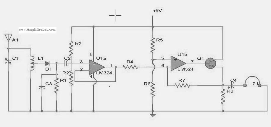
The following circuit illustrates a power amplifier electronic circuit, specifically a tube audio RF amplifier circuit diagram. This circuit is based on the LM324 integrated circuit. The power amplifier circuit utilizing the LM324 operational amplifier is designed to enhance audio...
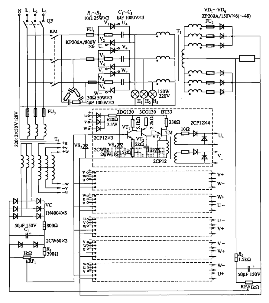
A three-phase thyristor power regulator circuit designed for plating applications, capable of handling currents from 1200A to 6000A at a voltage of 10V. The circuit comprises a main circuit, a trigger circuit, synchronous power components, and a voltage negative...
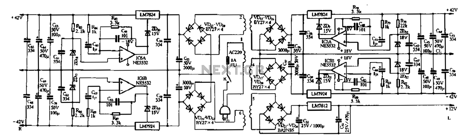
The F9500 serves as the power supply in the United amplifier circuit preamplifier. It utilizes an LM7824 and LM7924 configuration to create a 42V servo regulator power supply, incorporating the NE5532 operational amplifier for the servo circuit. In this...
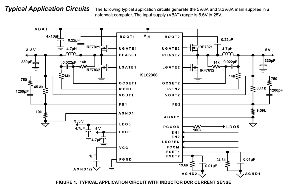
The ISL62386 controller generates supply voltages for battery-powered systems. It features two pulse-width modulation (PWM) controllers that are adjustable from 0.6V to 5.5V, along with two linear regulators, LDO5 and LDO3, which provide fixed outputs of 5V and 3.3V,...
It is possible to easily generate various non-linear functions such as X^(1/2), X^2, X^3, 1/X, XY, and X/Y using logarithms. In this context, division is transformed into subtraction, while multiplication is converted into addition. The application of logarithmic properties in...
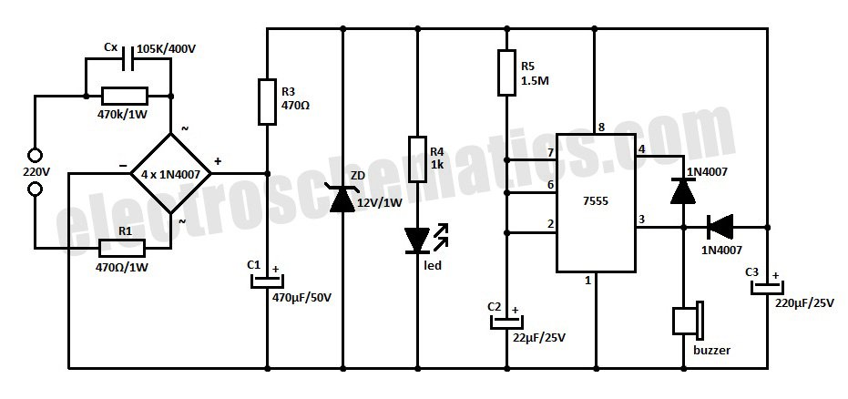
This is a simple power resumption alarm circuit that can be installed within the switch box. It emits beeping sounds when power is restored following a power failure. The power resumption alarm circuit is designed to provide an audible alert...