
Power 220V LED Flashing

This LED flasher circuit utilizes the TLC555 timer in an astable configuration to produce a continuous square wave output that drives a light-emitting diode (LED). The circuit is powered by the AC mains supply, which is stepped down to a safe level using a capacitive potential divider. This method is advantageous as it eliminates the need for bulky transformers, making the circuit more compact and efficient.
The capacitive potential divider consists of two capacitors in series, allowing a small amount of AC voltage to pass through while blocking the higher voltage levels. The output from this divider feeds into the power supply section of the circuit, typically involving a bridge rectifier and smoothing capacitor to convert the AC voltage into a stable DC voltage suitable for the TLC555 operation.
The TLC555 timer is configured in an astable mode, meaning it continuously switches between its high and low states, thereby turning the LED on and off at a defined frequency. The timing of the LED flashing is determined by the resistor and capacitor values connected to the timer. For instance, the frequency can be adjusted by varying the resistances and capacitance values, allowing for customization of the flashing rate according to application requirements.
In addition to the basic components, the circuit may also include a current-limiting resistor in series with the LED to prevent excessive current from damaging the LED. The output from the TLC555 can drive the LED directly, as the timer can source sufficient current for standard LEDs.
Safety considerations must be taken into account when designing this circuit, especially regarding the high voltage AC input. Proper insulation and enclosure are necessary to prevent accidental contact with live parts. Additionally, the use of components rated for the appropriate voltage and current levels is crucial to ensure reliable operation and longevity of the circuit.
Overall, this AC mains operated LED flasher circuit serves as an effective demonstration of using the TLC555 timer in practical applications, providing a simple yet functional solution for visual signaling or decorative lighting.AC mains operated single LED flasher circuit, built using the popular CMOS timer chip TLC555 is shown below. The whole circuit is powered directly by the grid supply of 230VAC through a capacitive potential divider and associated components..
🔗 External reference
Related Circuits

The following circuit illustrates the connection of the Devantech SRF04 Ultrasonic Sensor to the SV203 powered PPRK Circuit Diagram. This circuit is based on the Devantech SRF04 sensor and features a minimum initiation time of 10 milliseconds for the...
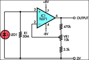
This circuit demonstrates the use of a standard LED as a light sensor. It utilizes the photovoltaic voltage generated across the LED when exposed to light. LEDs are more cost-effective than photodiodes and feature an integrated filter, which is...
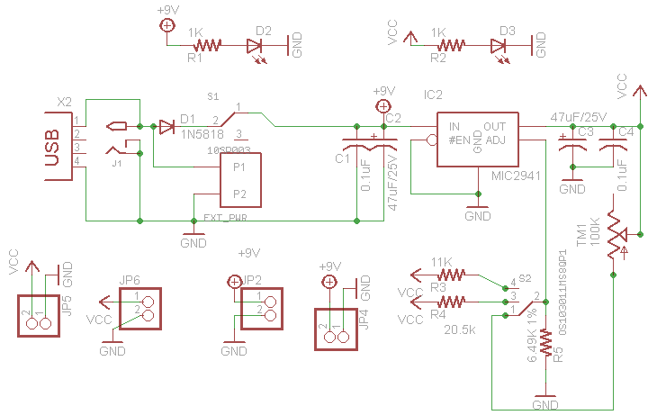
This project outlines the design of a very low dropout adjustable power supply. A reliable power supply is crucial for electronic projects. Although numerous existing designs for adjustable power supplies are available, this particular design introduces enhancements that increase...

This project demonstrates the construction of a simple LED light string display utilizing seven 24V LED light strings. The project was designed for Christmas 2009 to adorn a balcony with lights. The light strings are widely available, particularly in...
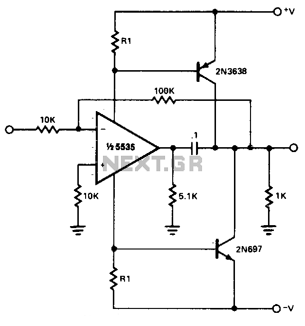
The power booster is designed to drive moderate loads. The circuit utilizes a NE5535 device. Other amplifiers may be substituted, provided that the resistor values (R1) are adjusted according to the Icc current requirements of the chosen amplifier. Additionally,...

The TPA3112D1 is a 25-W efficient Class-D audio power amplifier designed for driving a bridge-tied speaker. It incorporates advanced EMI suppression technology, allowing the use of cost-effective ferrite bead filters at the outputs while complying with EMC requirements. The...