
Power Amplifier 45W with HEXFET

An ideal solution for making a good, low-cost power amplifier. It's an ideal solution for creating a home cinema system. The preamplifier and the driver are supported in an operational amplifier [IC1]. The voltage drop in resistors R5 and TR2/R6 drives the output FET's gates and is proportional to the input signal level. Transistors Q1-2 function as voltage stabilizers in the supply lines, but also ensure the essential voltage drop because the IC1 should not be supplied with voltage greater than ± 18V.
Additional Content:
The circuit is designed with an operational amplifier (IC1) at its core, which serves as the preamplifier and driver. This operational amplifier is crucial to the circuit's functionality, amplifying the input signal before it is processed further. The resistors R5 and TR2/R6 are key components in determining the output of the circuit. They control the voltage drop across the output FET's gates, which is directly proportional to the input signal level. This means that changes in the input signal will result in corresponding changes in the output, ensuring accurate signal amplification.
The transistors Q1-2 play a dual role in this circuit. They not only stabilize the voltage in the supply lines, ensuring consistent power supply to the circuit, but also control the voltage drop across the IC1. This is vital as the IC1 should not be supplied with a voltage greater than ± 18V. Exceeding this voltage limit could potentially damage the IC1, leading to circuit failure.
This circuit design is an optimal solution for those looking to build a low-cost power amplifier or home cinema system. It provides a balance of cost-effectiveness and performance, making it a viable choice for both professional and amateur electronics enthusiasts. The circuit's design ensures efficient power usage and accurate signal amplification, key factors in the performance of power amplifiers and home cinema systems.A ideal solution for the make a good, low cost power amplifier. Its a ideal solution for the creation a system of home cinema. The preamplifier and the driver support in a operational amplifier [IC1]. The voltage fall in resistors R5 and TR2/R6, drive the output FET`s gates and is proportional with the input signal level. Transistors Q1-2 function as voltage stabilizers in the supply lines, but ensure also the essential voltage fall, because the IC1 it should not they are supplied with voltage bigger ± 18V.
🔗 External reference
Related Circuits
The design is based on the TubeHobby and serves as the power supply used in their NC2. This kit was constructed as an initial project involving nixie tubes, and a review of this excellent kit can be found in...
Both halves of the circuit are identical. Both inputs have a dc path to ground via the input 47k control which should be a dual log type potentiometer. The balance control is a single 47k linear potentiometer, which at...
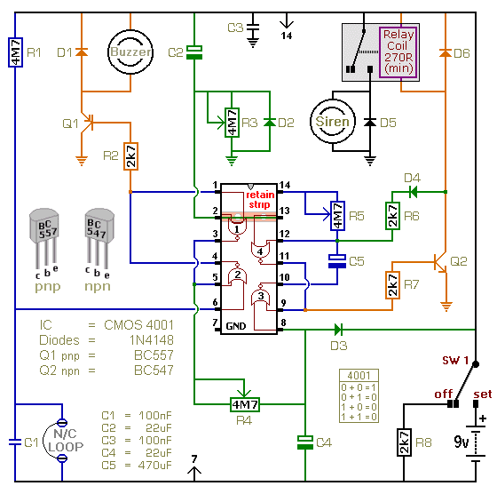
This is a single-zone alarm system featuring independently adjustable Exit, Entry, and Siren Cut-Off timers. It is designed to accommodate standard normally-closed input devices, such as magnetic reed contacts, foil tape, and passive infrared sensors (PIRs). The system can...
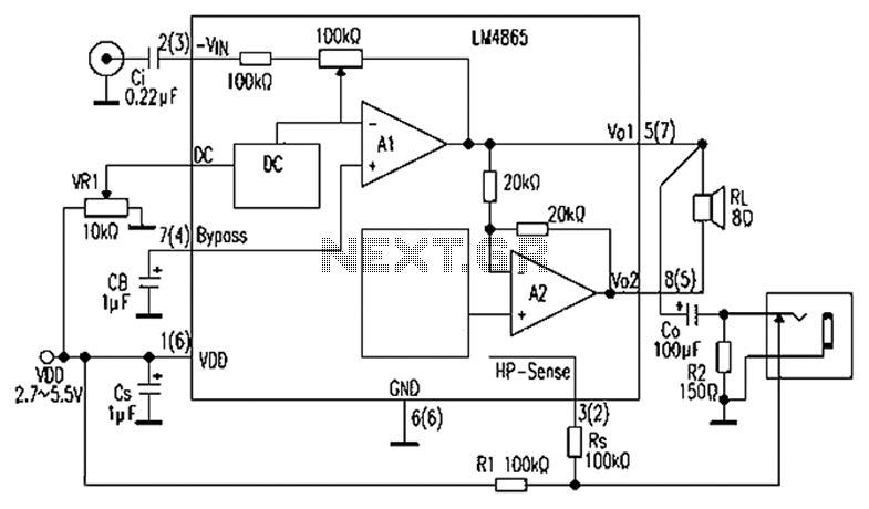
A 750mW bridge-tied load audio amplifier circuit utilizing the LM4065 amplifier is presented below. The LM4865 is available in an 8-pin SO package and an 8-pin mini SMD package. The power supply voltage (VDD) ranges from 2.7V to 5.5V,...
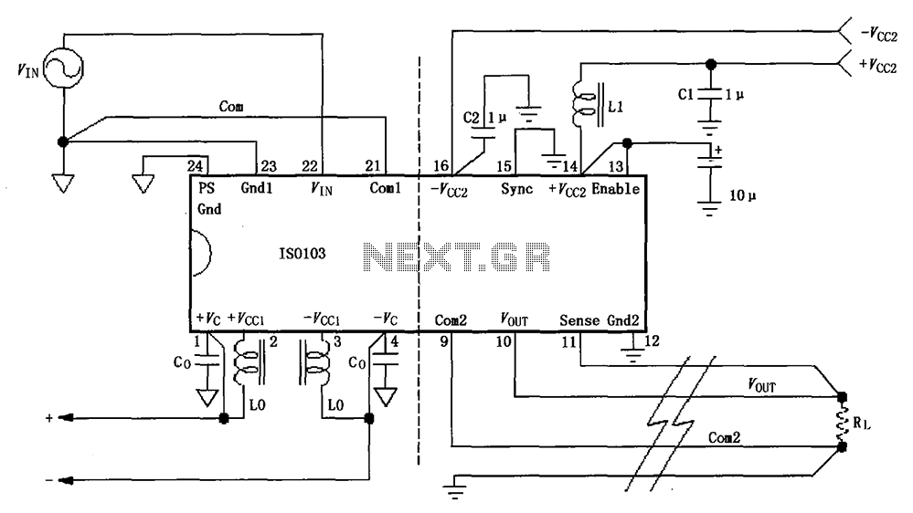
The basic connection circuit for the ISO103 signal and power supply is illustrated. Each power supply terminal must include a bypass filter. If the isolated power supply output current exceeds 15mA, it is advisable to utilize an external filter...
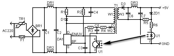
5 Volt/1.5A Switching Power Supply based on the TNY264P power supply. Refer to the designated page for an explanation of the related circuit diagram. The 5 Volt, 1.5A switching power supply utilizing the TNY264P is a compact and efficient power...