
3A Switching Power Supply

The 50W offline switching power supply circuit employs a MOSFET for efficient power conversion. The use of the BUZ80A/IXTP4N8 and GE IRF823 MOSFETs allows for compatibility with both 220V and 110V AC input voltages, ensuring versatility across different power supply environments. The output specification of 5V DC at 10A indicates that the design is suitable for powering devices requiring stable low voltage and high current, such as microcontrollers and other digital circuits.
In addition to the primary power supply circuit, the adjustable voltage regulator circuit utilizes the LM317HV, which is known for its ability to provide a stable output voltage across a wide range of input voltages. The inclusion of the 2N3792 power PNP transistor enhances the current handling capability, allowing the regulator to deliver up to 3A of output current. This feature makes the circuit applicable for various electronic projects requiring adjustable voltage levels.
The automatic switching-on emergency light circuit showcases an intelligent design that activates lighting in the event of a power outage. The control logic implemented through the dedicated IC ensures reliable operation, while the relay RL2 provides a seamless transition from mains power to battery power. The overcharge protection mechanism safeguards the battery from damage, extending its lifespan and improving overall reliability.
The 5V regulated power supply circuit is further enhanced by the integration of overvoltage protection components. The use of the 7805 regulator chip ensures that the output voltage remains stable at 5V, while the SCR 2N1595 and Zener diode 1N3997 work together to protect the circuit from voltage spikes. This design consideration is crucial for applications involving sensitive components, such as 74LS series integrated circuits, which require precise voltage levels to function correctly. The overall design reflects a comprehensive approach to power supply and regulation, ensuring reliability and performance across various electronic applications.The following diagram is the 50W offline switching power supply circuit design. The circuit powered by a MOSFET. BUZ80A/IXTP4N8 for 220V AC voltage input and GE IRF823 for 110V AC input voltage. The output will be 5VDC with electric current up to 10A. The schematic diagram: Component list: The schematic shows a 50-W power supply. Above circuit di agram is a easy, simple and cheap switching voltage regulator which has capability to deliver adjustable voltage output range of 1. 8V to 32V and static electric current of 3A. This regulator use adjustable regulator IC of LM317HV and a power PNP transistor of 2N3792. The LM317HV is adjustable 3-terminal positive voltage regulators capable. The schematic diagram shown right here is the automatic switching-on emergency light circuit which is controlled using IC.
The most important capabilities of this circuit are: automatic switching-on of the light on main power failure and battery charger with overcharge protection. When mains electrical power is absent, relay RL2 is in deenergised state, feeding DC. This is the circuit diagram of 5V Regulated Power Supply circuit, featured with over voltage protection.
The circuit is based regulator chip 7805; Thyristor SCR 2N1595 and Dioda Zener 1N3997 for overvoltage protection circuit. The 5V regulated power supply is apply 74LS series integrated circuits which has to be really precise and tolerant of voltage.
🔗 External reference
Related Circuits

The circuit depicted in Figure 3-121 illustrates the key component of an electromagnetic holding brake, which consists of an electromagnetic brake solenoid primarily made up of two parts: the iron core and the shoe brake components. When power is...
The circuit involves powering an LED using a 3V CR2032 battery, with the intention of extending battery life by making the LED blink rather than remain continuously on. A 555 timer is considered, utilizing large value resistors in the...
This circuit is intended to indicate the power output level of any audio amplifier. It is simple, portable, and displays three power levels that can be set to any desired value. IC1A is the input buffer, feeding 3 voltage...
The welder no-load power saver circuit consists of a current detection control circuit and a power saving control circuit, as illustrated in the accompanying chart. The current detection control circuit includes a current transformer (TA), a bridge rectifier (UR),...
A novel method of hydrogen generation through water electrolysis utilizing an ultra-short-pulse power supply is presented. The process of hydrogen generation via water electrolysis involves the splitting of water molecules (H2O) into hydrogen (H2) and oxygen (O2) gases using electrical...
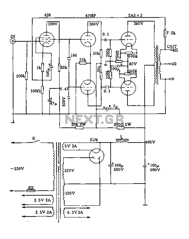
FIG. 2A3A is a low direct thermal resistance transistor with a resistance of only 800 ohms. The output transformer has a primary screen to load impedance of 3.5k ohms. The push-pull amplifier tube operates with a screen voltage ranging...