
Power Function Circuit

The application of logarithmic properties in electronic circuits can be highly beneficial, particularly in the context of analog signal processing and mathematical function generation. By utilizing operational amplifiers (op-amps) in conjunction with logarithmic and antilogarithmic circuits, it becomes feasible to create non-linear functions efficiently.
For instance, to generate the function X^(1/2) (the square root of X), a logarithmic amplifier can be employed to compute the logarithm of the input voltage (representing X). This logarithmic output can then be processed through an exponential amplifier to yield the desired square root function.
Similarly, for functions such as X^2 and X^3, the use of a logarithmic amplifier allows for the transformation of multiplication into addition. By configuring the op-amp circuit to add the logarithmic outputs of the input signal to itself, the circuit can effectively produce the square or cube of the input voltage.
Furthermore, for functions involving division, such as 1/X or X/Y, the logarithmic properties can simplify the process. By taking the logarithm of the input voltage, the division operation can be performed through subtraction in the logarithmic domain, allowing for efficient computation of the desired output.
Overall, the integration of logarithmic functions within electronic circuits not only facilitates the generation of complex non-linear functions but also optimizes the performance of signal processing applications, making it an invaluable technique in the field of electronics.We can generate easily many non-linear functions such as X^1/2, X^2, X^3, 1/X, XY and X/Y using logs. Division becomes subtraction, multiplication becomes. 🔗 External reference
Related Circuits
Circuit audio peak indicator circuit schematics. Circuit Electronics, schematics for audio peak indicator circuit. An audio peak indicator circuit is designed to visually represent the peak levels of an audio signal, providing critical information for audio engineers and musicians regarding...

A radio camera on a model railway should transmit constantly while the train is moving and continue transmitting for a few minutes after the train stops. The design of a radio camera system for a model railway requires careful consideration...
The inverter circuit diagram utilizing the NE555 timer is illustrated, designed to convert a +12V DC battery voltage into a 220V AC output voltage. In this circuit, the NE555 functions as an oscillator, with the oscillation frequency determined by...
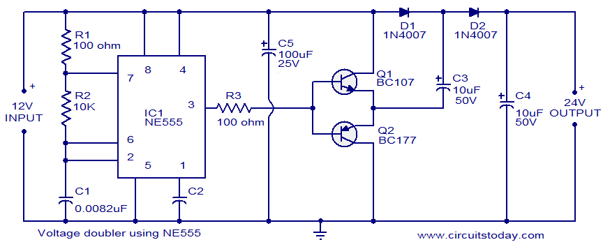
This circuit demonstrates a voltage doubler utilizing the NE555 timer. It is a straightforward project. The NE555 integrated circuit is configured as an astable multivibrator. The NE555 timer is a versatile component commonly used in various electronic applications, including timing,...
This is a simple 1.5V powered LED flasher circuit diagram. This circuit can flash 1.7V or 2.3V LEDs (depending on the color) using a 1.5V DC input. The LED will turn on when the 100µF capacitor is charged by...
The circuit operates with relevant components highlighted in the manual's draw mode. Figure A presents a circuit schematic, while Figure B illustrates a typical conventional secondary circuit layout. Figure E showcases an improved secondary circuit schematic diagram that incorporates...